The purpose of a schematic diagram is to record in a readable form an overview of the connections and function of a circuit. The evaluation of the quality of a scheme mainly depends on aesthetic factors that are little understood. The sections in the remainder of this document continue the description of the automatic schematic drawer.
The fourth section presents the performance of the program on two examples of digital arithmetic circuits. The purpose of a schematic is to highlight to the reader such aspects as signal flow, the circuit's main inputs and outputs, connectivity, module identities, and circuit function. Cataloged solutions for task-specific subproblems that are applied when the presence of subproblems is recognized.
Constraints placed on the task solution by virtue of the implements (read algorithms) that perform the design.
Related Research
Extensibility within a domain refers to the relative ease of adding new bits of knowledge to a program with at most localized changes to the initial domain knowledge, and no change to the inference/search mechanism. Extending across domains means using the same programmatic framework for a different task, replacing the new domain knowledge with the old.
Characteristics of the Domain and Problem-Solver
What Characteristics are Inherent?
Task Characteristics
Synthesis
There is freedom to fail
Does not use classification approach (does design)
Satisfices instead of optimizing
Conflicting subgoals are occasionally reconciled by adjusting one (or more) of them to remove the conflict
Demands a task where it is possible to write intelligible rules to fix conflicting subgoals
Characteristics of Human Problem-Solving
Does design
Satisfices
Uses both cognitive and perceptual skills
Performance takes a few minutes
Other Domains for Which Architecture Is Promising
Two Drafting Examples
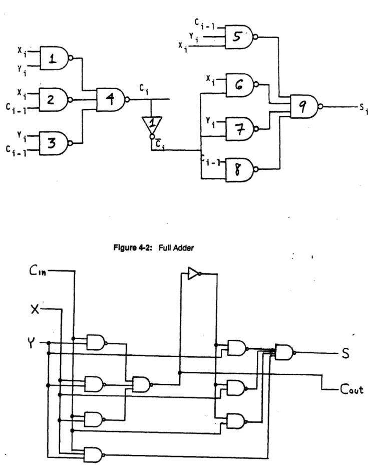
Binary Full Adder
The first circuit is a binary full adder using only NAND gates and an inverter, taken from a textbook on digital circuits [27].
Cout
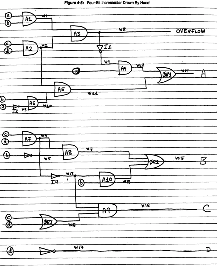
Four-Bit Incrementer
The second circuit, shown in Figure 4.4, increments a four-bit integer and outputs a four-bit integer and a carry bit. This incrementer was originally created to experiment with the diagnostic algorithms of the MIT Al Lab's Hardware Troubleshooting group. This author has drawn up the diagram in Figure 4.5 by hand, and has relied on it to trace signals and verify the diagnoses produced.
Although this manual schematic is not carefully done, it shows, in contrast to machine schematics, the advantage of automatic schematic drawing.
Execution Time
Program Architecture
- The Input
- The Output
- Where Is The Domain Knowledge?
- Representation Of The Domain Knowledge
- Need to infer spatial relationships between two objects that are implicit in a set of constraints
- The language should allow useful information (e.g. a nogood set) to be extracted when a contradiction occurs
For example, the assertion that a set of primary input signals constitutes the bits of an integer is useful information, as is the fact that two such integers are added to produce a third. There are two places where domain knowledge resides: in features and in adjustments. The features are found by simply iterating over all the signaling networks in the circuit, trying to classify each one, individually or in combination.
Objects are sorted by priority, and this order is followed when applying object constraints to the current partial layout. Introspection and study were responsible for the traits themselves, and occasionally the disjunctive statements of the traits were changed after experiments showed that they too often led to conflicting interactions with other traits. Whenever a contradiction was easy to correct, its correction was added to the corrections if the correction seemed general instead of a.
As a trade-off, we'll only allow distance constraints that refer to one of the axes, so that each constraint contains only two variables (distance constraints along a diagonal must reference four variables). It is known that a set of simple linear inequalities like (1) is mapped to a graph, where the nodes are the variables and the directed edges are weighted by the inequality constant. A set of inequalities is consistent if numbers (integers in this case) can be assigned to variables such that all inequalities are consistent.
Since integer assignments to variables are the only output, we cannot ask whether IN-1 is necessarily to the right of IN-2 in any layout derived from the current one. 10 The common name is a single-source shortest path algorithm where the objective is to find the shortest path from a specified 'ceiling' variable to all other variables. By reversing the direction of the inequality in the algorithm, we find the longest path instead of the shortest.
OBTI
For example, the distance between diagonally opposite points of a unit square is 2, not the square root of 2. Our language must allow for the expression of maximum and minimum distances between pairs of objects. We note that the equality of two quantities can be expressed by the combination of two inequalities.
The Single Source Longest Path (SSLP) algorithm1o determines the consistency of a graph by assigning integers; if after a certain number of repetitions some are left violated. However, we do not use this algorithm because its output does not allow searching for spatial relationships between pairs of objects. If SSLP assigns 5 to the x-coordinate of AND-1 and 4 to the x-coordinate of AND-2, at most we know that AND-2 is not necessarily to the right of AND-1.
To search for connectivity between any pair of objects, we need to compute the longest paths between all pairs of nodes, not just from a single source. The All-Pairs Longest-Path (APLP) algorithm computes transitive closure [3] of the graph; makes clear all relationships between pairs of nodes that implicitly hold through transitivity. With these longer paths, we can answer questions about the spatial relationship between any pair of objects.
SND-5
- The Search Regimen
- Fixes: Resolving Contradictions
- System Diagram
- The Backtracking Scheme
The violation of said preview constraint is checked by finding out whether a third object shares the same y-coordinate as the pair of objects and whether its x-coordinate is constrained to be between the pair. A transitive contradiction is a logical absurdity that can be interpreted as an object being above itself by virtue of the constraints. A fuller discussion of the algorithms used in our program, along with theorems on their incremental properties, is in MIT Al Lab Memo 875 written by this author [44].
The program applies each of the features detected in the circuit to narrow down the possible layouts. The search regime adopted here selects a feature at each turn, and imposes one of the sets of constraints, out of several possible ones, by adding the inequalities to the set. If a conflict between the constraints contributed by these features is obscured by other conflicts, the prerequisites of the solution may not be met.
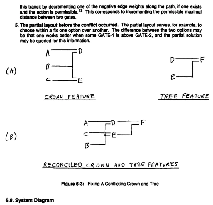
An example of using the nogood set to resolve a conflict is when the conflict involves only a canopy and a tree, as shown in Figure 5-3a. This transition in the y direction can be removed by transforming the crown as shown in Figure 5-3b.1 2 If there is a transition, the sum of the edge weights along the closed path. Using a feature on a partial layout involves selecting one of the options associated with that feature.
Any functions that were skipped during the backtracking should be reset as indicated because these choices depend on a partial layout that will no longer exist. While browsing the current feature, when a selection conflicts with the current partial layout, the search simply updates the current feature's return list and the next selection is attempted. If the schema is good, it should make the most of the information provided by the contradictions.
SEP1
SppLYR,.-
- Summary
- Performance Analysis
- Why Does The Program Work?
- Program Competence - Knowledge
- Program Competence - Architecture
- Work To Be Done
- Conclusion
- Achievements Of This Research
- A Computational Theory of Drafting
- Notable Aspects
- A knowledge-based system that designs schematic layout using an architecture that maintains a distinction between its domain knowledge and the search framework
The formalized reasoning presented here does not accurately reflect our architecture, due to the corrections that may insert choices spontaneously. Disjunctions of the type T, v T2 have, in theory, an unlimited number of disjuncts, obtained by combining the corrections. To provide a formal justification for the backtracking scheme, we would need first-order predicate calculus statements.
Instead, we will rely on the intuitive correctness of the approach for this more complex case. As befits a knowledge-based program, the domain knowledge is different from the control of the search. This author argues that the program works because it captures some of the reasoning that people do while constructing a circuit.
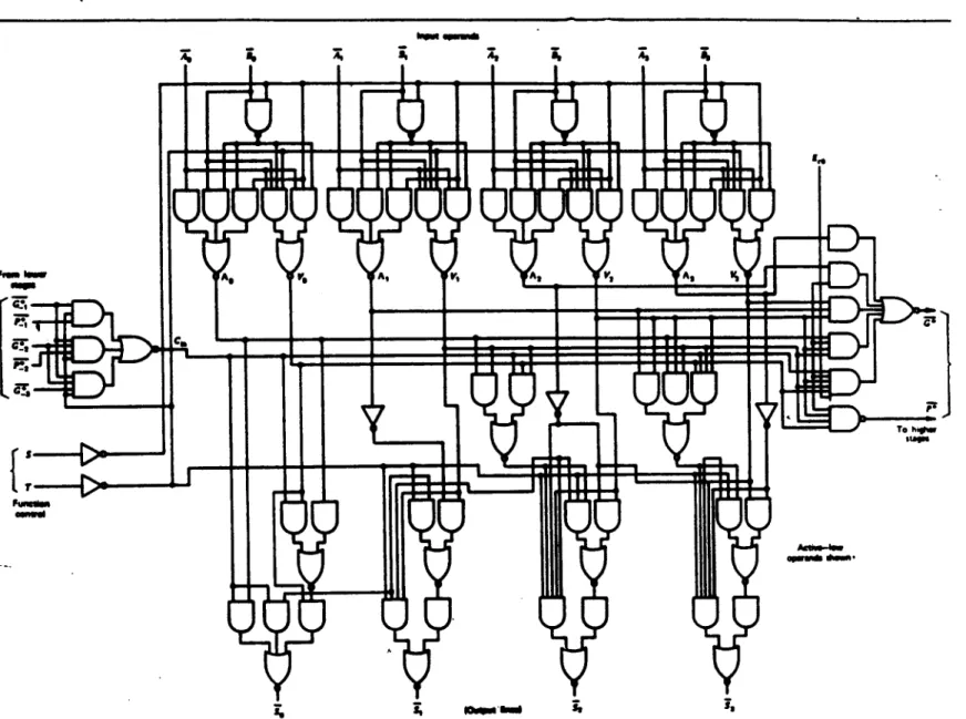
Even assuming these are given by hand, the problem of formulating a plan remains. Figure 4.9 The schematic logic diagram of a 4-bit ALU with carry lookhead as specified in Figure 4.8. The result is a program that, in the form of the layouts described in this report, has demonstrated skillful drawing within the domain of arithmetic digital circuits.
Accordingly, we then extract from our program an abstract description of its behavior, independent of the algorithms that implement the behavior. This search space is not static at the OR level, because in general the number and nature of the disjoints depend on the state of the query (partial layout) so far. Conflict recovery can be seen as the spontaneous insertion of disjoints at the OR level of the tree.
Acknowledgment
The Features
- Feature Definitions
- tripod. A head gate G is fed only by 3 gates, which in turn feed no other gate besides G
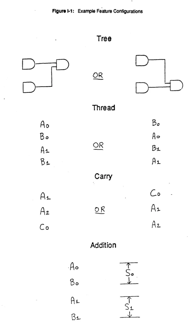
Of these, 11 concern only the connections or topology of the circuit, and can be seen as general features of a directed graph. Each bit of the sum is placed vertically between the corresponding bits of the two sums. Next come the topological features, which only concern the (directed) graph properties of the circuit.
One port G is fed by N>3 ports, and these N ports supply no ports other than G. One of the N ports is chosen as central, and its vertical position is aligned with G. The rest of the N-1 ports go either all vertically above or all vertically below the central gate.
The three tailgates feed no other ports, and the main doors are fed by no other ports. One of the three tailgates (the center) feeds both heads, and the other two tailgates (the wings) only feed one of the heads. One of the 2 feed ports is chosen to align vertically with A and the remaining port is placed either above or below the other two.
The signals involved in this function are the primary inputs and outputs of the circuit. We draw trees asymmetrically by vertically aligning one of the two feed ports with the head. This feature is drawn symmetrically by centering one of the 3 feeders and placing one of the remaining two gates on each wing.