I authorize Ryerson University to release this thesis or dissertation to other institutions or individuals for research purposes. The objective of the project was to design a small wind turbine blade that is aerodynamically efficient and easy to manufacture. The blade geometry was determined after calculating basic geometric values for low drag, which was then used to calculate power.
Overall, the project was successful in designing a wind turbine blade that produced 450 [W] of electrical power at 4[ml] wind speed with a starting speed of about 2[ml]. The project met its objective of designing a more effective wind turbine blade with manufacturability in mind. I would also like to thank my friend, Mohsin Afridi, for his help in my project.
Finally, I would like to thank Ryerson University for the opportunity to continue my graduate studies.
Introduction
Project Objective
- Benchmarking
- Requirements
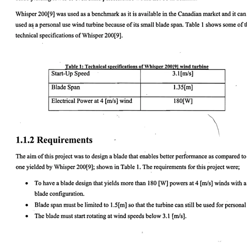
To get an idea of the performance of the designed blade, an existing small wind turbine was used for comparison. A benchmark was set to compare the performance with the existing design so that the new design would be acceptable in the market. The Whisper 200[9] was used as a benchmark as it is available on the Canadian market and can be used for a personal wind turbine due to its small wingspan.
The aim of this project was to design a blade that enables a better performance compared to - that given by the Whisper 200[9]; shown in Table 1. Having a blade design that provides more than ISO [W] effects at 4 [mls] winds with a 3-blade configuration. The wingspan must be limited to 1.5[m] so that the turbine can still be used for personal use.
Literature Survey
Analysis of the governing equations of wind turbine performance was an integral part of the project. Young [13] demonstrates the use of aerodynamic equations to determine the torque of the designed blade. Research was done to get a general idea of the whole concept of designing a wind turbine blade to get an idea of what to expect.
Raymer [6] and Young [13] explained the structural analysis process that can be applied when dealing with a wind turbine blade. The project is to design an efficient blade for small wind turbines to produce a better power than those available in the market. Overall, the literature survey was successful in determining the project's literature requirements while establishing a benchmark against which to compare.
The survey validated the results for airfoil selection while some of the geometric parameters were extracted from the literature.
Theory
This section of the report focuses on the design considerations and analyzes performed to achieve the optimal design for the blade. One of the safety considerations that must be included in the design is the ability of the blade not to exceed the maximum design operating speed of rotation. To estimate design parameters, the literature was reviewed to establish baseline values for blade geometry.
It is the tangential inverse of the ratio of the airspeed to the tangential speed of the blade section. Once the lift coefficient was determined, the total lift generated by the blade was determined using the following equation;. To keep the starting speed low, it was necessary to keep the weight of the blade as low as possible.
The starting speed is directly dependent on the weight of the blade and the lift generated. The lift decreases as the flow separation point marches forward, stopping the tip portion of the blade. Spanwise chord was calculated after determining the aspect ratio and taper ratio of the blade.
Further reduction of the blade thickness is not possible without changing the material or shape of the blade. The starting speed of the wind turbine blade was determined by the total weight of the blade. To calculate the starting speed, it is taken into account that the blade is at rest, i.e. so that it does not spin.
Due to the non-rotating blade approach, most of the blade will have stalled, except for the section near the root. Using the lift equation, different wind speed values were used to determine lift for the part of the wing closer to the root.

Blade Design
Aerodynamics .......................................................................... "
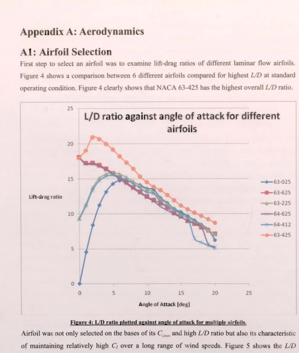
- Airfoil Selection ....................................... "
- Blade Geometry
- Blade Analysis ................................. ! .......................................... _
Aerodynamics plays the most important role in the design of a wind turbine as it determines the total lift, i.e. the overall power production capability of the blade. This section provides an overview of airfoil selection considerations, blade geometry analysis along with general blade aerodynamic analysis. Finally, airfoils were compared for their high effect·CLmax• pitching moment was considered negligible due to the small blade geometry and low operating Reynolds number.
For thin airfoils, the flow separation .. point begins to move toward the leading edge as the wind speed increases, stalling the tip section of the wing and thus reducing overall lift. The airfoil at the tip of the blade had to be thin enough to stall at high wind speeds, yet thick enough not to cause a sudden stall. After careful consideration and performing airfoil analysis using JavaFOIL [16] and DesignFOIL [15], it was decided to use NACA 63-425 for the root and NACA 63-415 for the wing tip.
Due to the above-mentioned consideration, the design angle of incidence of the wind turbine blade was chosen to be 7 [°]. Aspect ratio is the ratio of the vane span squared to the planar area of the vane. the equation relating aspect ratio to other geometric parameters is as follows; e.q. 11) It has been found that the aerodynamic trend is towards a high aspect ratio because it is an effective way to reduce drag. This occurs because the blade would already be operating at the highest local C, so it would stall at high speed.
The tip speed ratio is defined as the ratio of the blade tip speed to the free stream. Although there is an equation for determining blade twist, the values determined using the equation are not the most optimal for a small blade design. The next section discusses the 3-D aerodynamics approach and its implementation to determine the lift, drag, and torque for the blade.
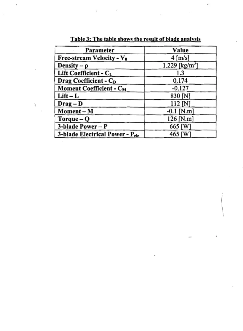
With the aerodynamic parameters known, the next step was to find out the total power generated by the wing. EquationlO suggests that in order to find out the power generated by the blade, the toque, Q, must be determined, which can be described as follows;. e.q. 19) The equation gives the result for the torque produced by the blade.

Results .............................................................................................................. _
Since power is the product of torque and angular velocity, iterations were performed with respect to tip velocity and freestream wind. The result of the repetitions was an average value for angular velocity, which was then used to determine power. It was also desired to determine the electrical power output to compare the design with other competitors.
For this purpose, it was assumed that one third of the power is lost in the process of conversion from mechanical to electrical energy.
Structures
Material
Stress Analysis
Manufacturing
- Procedure - Cutting
- Procedure - Moulding
Conclusion
Discussion
Although the designed blade was more efficient than the existing small wind turbine blades, it can be further improved. The blade has a safety factor of 6 which indicates that the blade is structurally strong enough to safely support more load. Improvements can be made in the blade design by increasing the tip chord which will produce more torque and subsequently more power.
An inexpensive low strength fiber can also be used for the same blade geometry to reduce overall cost.
Concluding Remarks
This fluctuation and sudden drop in lift is undesirable as it will disable the blade from operating over a variable range of wind speeds and angle of attack. Using Equation 19, span wise torque was plotted against span and the equation of the curve was determined as shown in Figure 12. The established equation was integrated over the blade span to determine the total torque which was then used to calculate total power.
Since the vane twist angles were finalized and the freestream velocity value was known, the tip velocity values were repeated to satisfy the relative tip velocity. A rectangular quadrilateral element, Shell 99, with six degrees of freedom per node, dealing with linearly layered composite shell structures, was used to determine the stress experienced by the blade. The use of a total moment at the tip was made to test the blade for extreme conditions and for a conservative design.
Although the maximum load experienced by the blade falls well below the ultimate stress value of E-fiberglass-epoxy, the structural design of the blade cannot be further optimized. The composite material to be applied to the blade can only be applied in quantum numbers, while the tested design has a single layer of E-glass fiber epoxy aligned longitudinally spanwise. The value is considered reasonable as any structure around the blade would be further away.
As shown in figure 15, the maximum deflection due to rotation is at the tip as the tip of the blade is free to move in any direction, unlike the root which is fixed at the centre. The blade experiences maximum stress, which is well below the ultimate stress limit of E-fibreglass-epoxy. The total weight is calculated using the volume of the blade and the density of the two different materials used, which is shown in Table 13.
By looking at the blade bend angles and comparing it to the rise of the bend slopes, the stalled section of the blade was estimated. The wind speed for which the total lift value corresponded to the blade weight value was defined as the starting speed. So the airfoil used for the blade diffuser is NACA 63-425 which means it is a series 6 airfoil having a minimum thrust of 30% of the back chord length with a lift coefficient of 0.4 and a maximum thickness of 25% of the cord.
In comparison, the airfoil used for the blade tip, NACA 63-415, has a maximum thickness of 15% chord length compared to 25% for the hub section.