HEXAALUIMINATE-TYPE CATALYSTS FOR N2O ABATEMENT
Marta Santiago Redondo
ISBN: 978-84-693-8864-8 Dipòsit Legal: T.1943-2010
ADVERTIMENT. La consulta d’aquesta tesi queda condicionada a l’acceptació de les següents condicions d'ús: La difusió d’aquesta tesi per mitjà del servei TDX (www.tesisenxarxa.net) ha estat autoritzada pels titulars dels drets de propietat intel·lectual únicament per a usos privats emmarcats en activitats d’investigació i docència. No s’autoritza la seva reproducció amb finalitats de lucre ni la seva difusió i posada a disposició des d’un lloc aliè al servei TDX. No s’autoritza la presentació del seu contingut en una finestra o marc aliè a TDX (framing). Aquesta reserva de drets afecta tant al resum de presentació de la tesi com als seus continguts. En la utilització o cita de parts de la tesi és obligat indicar el nom de la persona autora.
ADVERTENCIA. La consulta de esta tesis queda condicionada a la aceptación de las siguientes condiciones de uso: La difusión de esta tesis por medio del servicio TDR (www.tesisenred.net) ha sido autorizada por los titulares de los derechos de propiedad intelectual únicamente para usos privados enmarcados en actividades de investigación y docencia. No se autoriza su reproducción con finalidades de lucro ni su difusión y puesta a disposición desde un sitio ajeno al servicio TDR. No se autoriza la presentación de su contenido en una ventana o marco ajeno a TDR (framing). Esta reserva de derechos afecta tanto al resumen de presentación de la tesis como a sus contenidos. En la utilización o cita de partes de la tesis es obligado indicar el nombre de la persona autora.
D
OCTORAL
THESIS
H
EXAALUMINATE
‐
TYPE
CATALYSTS
FOR
N
2
O
ABATEMENT
M
ARTA
S
ANTIAGO
R
EDONDO
S
UPERVISED
BY
P
ROF
.
D
R
.
J
AVIER
P
ÉREZ
‐
R
AMÍREZ
ICIQ
‐
URV
T
ARRAGONAJavier Pérez‐Ramírez, Full Professor and Chair of Catalysis Engineering at the
Institute for Chemical and Bioengineering, ETH Zürich, Switzerland.
CERTIFIES:
That the present research study, entitled ‘Hexaaluminate‐type catalysts for N2O
decomposition’, presented by Marta Santiago Redondo for the award of the degree
of Doctor, has been carried out under my supervision at The Institute of Chemical
Research of Catalonia (ICIQ), Tarragona, Spain.
Zürich, September 2010
Prof. Dr. Javier Pérez‐Ramírez
Acknowledgments
En primer lugar, me gustaría agradecer a mi supervisor el Prof. Dr. Javier Pérez‐
Ramírez la oportunidad que me ha brindado al permitirme compaginar mi trabajo
en el ICIQ con la elaboración de esta tesis y al tiempo dedicado para que yo creciera
científicamente. También, por la confianza demostrada al contar conmigo para tu
nuevo proyecto en el ETH en Zürich.
A cada uno de los miembros del tribunal por aceptar formar parte del mismo.
Al director de l’Institut Català d’Investigació Química, Prof. Dr. Miquel Pericàs per
deixar‐me fer la defensa de la meva tesi fins la que fa poc era també casa meva and
also to Prof. Dr. Evgenii Kondratenko and Dr. Johan Groen for all the nice
collaborations we had during the last years.
Durante estos años en la URV y en el ICIQ, he conocido muchas personas que me
han ayudado en el día a día muchísimo y a las que no quisiera dejar de agradecer: En
especial a Anton, Esther, Eduardo, Simona, Enrique, Susana (Merci chic@s! por
hacerme la vida más fácil!) Al los chicos de compras, a los informáticos,
mantenimiento, a Maria y su bon día y a las “secres”, en especial a Beatriz porque
siempre está dispuesta a hacer lo que le pidas con una sonrisa! Y eso no tiene precio!
També a Mercé Moncusí i a la Rita de microscopia, sempre ajudant‐me a fer
aquestes fotos tant maques!
A todos los compañer@s y amig@s que he tenido en el laboratorio de los
heterogéneos en todos estos años; chic@s hemos sido una gran familia!
A Sònia y Yolandita! Por ser además de grandes compañeras, grandes amigas!!!
Gracias por todas las risas, conversaciones, confidencias y por estar ahí siempre
apoyando, ya sabéis que os valoro mucho tanto científicamente como
personalmente! Mucha suerte! A Miguel, el asturiano serio del piso de abajo!
Gracias por tu ayuda y tus consejos! Tú sí que eres un FIERA!
A Georgiana por haber compartido después de Tarragona conmigo los primeros
meses en Zurich, por tu amistad, por tu ayuda en el día a día y por no dejarme sin mi
rosa de San Jordi. No lo voy a olvidar!
Blaise, Ceci, Maria, Sharon, Amol and Danny.: Thanks for the good moments!
A mis amigos de siempre y para siempre: Esther, tet no sabes cómo te echo de
menos bandarra! Eva, Meritxell, Raquel, Jorgina, Nuria y Xavi. Chic@s sois
estupendos!
Por último sólo dedicar mi tesis a mi familia entera, a los que están y a los que ya
se fueron… en especial a mis padres, a mi hermano, a chimo y a ti porque tú me
completas.
The Spanish MICINN (CTQ2006‐01562/PPQ, AP2005‐5147, and Consolider‐
Ingenio 2010, grant CSD2006‐0003) and the ICIQ Foundation are acknowledged for
the financial support of this research.
Marta Santiago
Contents
Chapter 1
Introduction
1
Chapter 2
Synthesis and thermal activation of dawsonite‐type
compounds to oxide catalysts
13
Chapter 3
Decomposition of N2O over hexaaluminate‐type catalysts
33
Chapter 4 Carbon‐templated hexaaluminates with enhanced surface
area and catalytic performance 49
Chapter 5
Evaluation of catalysts for N2O abatement in fluidized‐bed
combustion
77
Chapter 6
Mechanism and micro‐kinetics of direct N2O decomposition
over BaFeAl11O19 hexaaluminate
93
Chapter 7
Summary and Outlook
115
List of Publications 121
About the author 123
Chapter
1
Introduction
CHAPTER 1. INTRODUCTION
A brief introduction of the state‐of‐the‐art N2O abatement in the chemical industry is
presented. The chemical industry and energy processes represent 39% of all the
anthropogenic nitrous oxide emissions and only emissions from these sources can be reduced
in the short term. Catalytic decomposition is the most widely used N2O abatement method.
Several catalysts based on bulk, supported and unsupported metals, pure and mixed oxides,
and metal‐loaded zeolites have been studied, however, only a few of them showed reasonable
performance under realistic conditions. The research described in this thesis focuses on the
development of a new family of catalysts based on metal‐substituted hexaaluminates, showing
excellent qualities for high‐temperature N2O abatement under simulated conditions. This
1.
Nitrous
oxide
Nitrous oxide (N2O), often referred to as laughing gas, is recognized as a harmful
gas causing adverse effects on our environment. In recent decades, atmospheric
concentration of this gas has been increasing at roughly 0.25% per year [1], and
unfortunately it appears that this trend will not be changed easily. Scientists (and
politicians) widely accept that N2O contributes to the enhanced greenhouse effect, a
natural phenomenon caused by absorption of infrared radiation in the atmosphere
reflected from the surface of the earth [2]. Figure 1 shows the distribution of global
anthropogenic greenhouse gas emissions in 2004.
Although nitrous oxide does not seem to be a major contributor to global warming
(7.9%) [3], its presence in the atmosphere is much more dangerous and worrying than
the other two common anthropogenic greenhouse gases, CO2 and CH4. Primarily,
because of its higher Global Warming Potential (GWP) (310 and 21 times more potent
than CO2 and CH4, respectively) and atmospheric lifetime of 150 years; and additionally
for being the single most important ozone‐depleting emission agent during 21st
century [4].
Atmospheric N2O emissions are produced by both natural and anthropogenic
sources. About 70% is emitted by bacterial breakdown of nitrogen in soils and oceans
while the remaining 30% is due to the human activities [1]. Within the anthropogenic
F‐gases 1.1%
CO2 (fossil fuel use)
56.6%
N2O
7.9%
CH4
14.3%
CO2 (deforestation,
decay of biomass, etc) 17.3% CO2 (other)
2.8%
Figure 1. Share of different anthropogenic greenhouse gases in total global emissions in 2004.
sources, agricultural practices and activities contributes to 61%, chemical industry
represents 29%, and combustion, including human sewage and burning of biomass and
biofuels, the residual 10%. Since control of N2O emissions from agriculture is difficult
to assess, only emissions from chemical industry and energy processes can be reduced
in the short term [5].
2.
Overview
of
present
technologies
N2O abatement strategies differ depending on the stringency of emission
regulations, and on the complexity of developing an effective technology for each
process. One of the most suitable methodologies is the catalytic decomposition where
a solid surface facilitates the cleavage of the N‐O bond in the nitrous oxide molecule
leading to harmless N2 and O2. However, several aspects should be taken into account
when designing de‐N2O catalysts i.e. the N2O content, location in the plant,
temperature, gas flow, pressure and feed composition. NOx, O2, SO2, and H2O are
commonly present in waste streams in addition to nitrous oxide, acting typically as
inhibitors or poisons, thus reducing the activity of catalysts or suppressing it
completely. Unfortunately, a one‐solution‐fits‐all does not exist, and the catalytic
system has to be optimized to the specific source and emission point in which the
abatement is practised [5]. A number of catalysts based on bulk, supported and un‐
supported metals, pure and mixed oxides, and metal‐loaded zeolites have been
reported in the literature [6]. Nevertheless, almost all studies have been typically
performed under unrealistic conditions limiting the practical design of a catalyst for a
real source. Reducing the gap between laboratory reaction models and real conditions
is vital, and therefore the evaluation of catalysts under practically‐relevant conditions
becomes necessary.
In chemical industry, the two most significant sources of nitrous oxide emissions
are nitric acid (NA) and adipic acid (AA) production. Global nitrous oxide emissions
from these two sources accounted for more than 154 million metric tons of carbon
dioxide (CO2) equivalent (1 kg N2O = 310 kg CO2‐eq) (Figure 2) in year 2000. It is
estimated that the global nitrous oxide emissions from these sources are expected to
Other sources are associated with chemical processes using nitric acid as oxidizing
agent or those involving ammonia oxidation steps (caprolactam, glyoxal) [8,9].
Emissions related with the latter sources are not conveniently quantified and
predicting their impact remains complicated. Regarding energy processes, the global
N2O emission from fossil‐fuel combustion is estimated at 60‐160 Mton CO2‐eq per year
[6], without taking uncertain emissions from biomass and waste combustion into
account. In the next sections, the state‐of‐the‐art catalytic technologies for N2O
abatement are concisely reviewed.
2.1.
Adipic
acid
production
Adipic acid is mainly used as the precursor in the production of Nylon 6,6 with an
annual world production of 2.7 Mton per year. N2O is generated during the oxidation
of cyclohexanol‐cyclohexanone mixtures with nitric acid. The most notorious feature of
this source is the high content of N2O 25‐40 vol.%, simplifying the problem to finding a
catalytic or thermal abatement process, since N2O decomposition is an exothermal
reaction.[5] One common practise for concentrated N2O streams is to dilute the inlet
N2O stream with air to control the temperature rise in the catalyst bed and to
guarantee safe and stable operation.
140 145 150 155 160 165 170 175 180
Mt
C
O2
eq
2000 2005 2010 2015 2020
Year
Figure 2. Global nitrous oxide emissions from nitric acid and adipic acid production 2000‐2020.
Source: EPA: Global Anthropogenic Non‐CO2 Greenhouse Gas Emissions: 1990‐2020, June 2006
Adipic acid was the major source of N2O emissions in the chemical industry until
2003. Major worldwide adipic acid producers organized a consortium targeting the
voluntary reduction of N2O emission either by thermal or catalytic N2O decomposition
which resulted in more than ~90% reduction [10].
The technologies in use so far for N2O abatement in adipic acid manufacturing are
CuAl2O4/Al2O3 and Ag/Al2O3 by BASF, CoO‐NiO/ZrO2 by DuPont, and CuO/Al2O3 by
Asahi Chemical [11]. On the other hand, other attractive strategies to catalytic and
thermal methodologies have also been proposed: the integration of adipic acid and
nitric acid plants [12,13] implemented in the BASF’s adipic acid and nitric acid plants in
Ludwigshafen (Germany), and the reutilization of N2O as a valuable oxidant to oxidize
the benzene to phenol developed by Solutia and the Boreskov Institute of catalysis
[14]. After the implementation of catalytic systems, limited progress has been
achieved. Only Alini et al. [15] claimed AB1−xB’xO3 perovskites with A = La or Ca, B = Mn
or Fe, and B’ = Cu or Ni as a possible candidate under realistic conditions.
2.2.
Glyoxal
and
glyoxylic
acid
production
Glyoxylic acid is used as a key intermediate in the Pharma or Agro industries. It is
used in the manufacturing of synthetic Vanillin and ethyl Vanillin, in the syntheses of
widely used antibiotic, Amoxycillin and as a starting material for the synthesis of iron
chelates, a product group used as micronutrient in the Agro industry.
Clariant at Lamotte, France is the only known manufacturer of glyoxal and glyoxilic
acid where the production process gives rise to N2O emissions. The company is also a
pioneer in the application of N2O abatement technology in glyoxal production. Thermal
treatment system, promoted by specific catalyst, an ion‐exchanged Fe‐ferrierite
patented by Grande Paroisse [16], is used in the abatement. In this treatment, the N2O
content in the tail gas (85 vol.%) is diluted to ca. 10 vol.% by air at the inlet of the
process to control exothermally the reaction and allowing safe and stable operation of
the catalyst. The adiabatic temperature rise in the reactor, 200 K, is used to preheat
the inlet tail‐gas up to 675 K. (It is known that N2O is a very stable gas which requires
performance target in N2O mitigation). The system reaches a decomposition rate of
over 95% of N2O when the catalyst is fresh [10].
2.3.
Nitric
acid
production
Nitric acid is a widely produced basic chemical throughout the world. It is a key
ingredient in ammonium nitrate fertilizers, nitrate explosives, and various complex
acid products. N2O is formed as a by‐product in Ostwald reaction. Due to the different
operation conditions, the abatement technology implemented with success in adipic
acid plants (~90% emission reduction either by thermal or catalytic N2O
decomposition) cannot be extrapolated to nitric acid production. The relatively low
N2O concentration in nitric acid plants (in the order of 1000 ppm) and the presence of
abundant inhibitors (H2O, NOx and O2) made the development of active and stable
catalyst systems essential for this application. As reviewed by Pérez‐Ramírez et al. [5],
N2O abatement at different locations in the nitric acid plant was extensively
investigated during the last decade.
As a result of the studies, direct N2O decomposition below the noble metal gauzes
in the ammonia burner (process‐gas option) and in the tail‐gas train (tail‐gas option)
were concluded to be cost‐effective abatement measures for existing plants, and the
major producers of nitric acid started the development of new catalytic systems.
In the process‐gas option, the three catalytic systems described in the patent
literature and developed by the industry mainly relates to supported spinels and bulk
perovskite: CuO/Al2O3 by BASF [17], La0.8Ce0.2CoO3 by Johnson Matthey [18],
Co2AlO4/CeO2 by Yara International [19]. The major advantage of process‐gas
decomposition is the universal application in all nitric acid plants.
In the tail‐gas, Uhde commercialized EnviNOx process for the combined removal of
N2O and NOX in a single fixed‐bed reactor by use of iron‐containing zeolites. However,
this option is limited in plants with tail‐gas temperature >700 K, since the use of Fe‐
zeolites at lower temperatures is prohibitive without the presence of reducing agents
and gas preheating.[5,20].
Several catalytic systems have been studied in the last decade for being an
number of papers and patents claiming higher activity for N2O decomposition were
published but these systems failed to be considered as serious alternatives due to the
‘ideal’ conditions taken into consideration during the studies.
In the process‐gas, very recent studies investigating ABAl11O19 hexaaluminates with
A = Ba or La and B = Fe, Mn, Co, or Ni [21], α‐alumina‐supported iron oxide [22], and
mayenite [23] can be found. In the tail‐gas, only extra‐framework Fe‐ZSM‐5 [24‐26]
showed remarkable activity and stability in simulated tail‐gas mixtures.
2.4.
Caprolactam
production
Caprolactam is an intermediate primarily used in the production of Nylon 6 fibers
and resins. The principal routes for the production of caprolactam are HPO
(hydroxylamine phosphate oxime) and HSO (hydroxylamine sulfate oxime) where N2O
is formed as a by‐product at different points of the process.
Until now, the uncertainty in annual N2O emissions from caprolactam production
has been estimated at about 70% and reduction measures are not available yet [10].
There are many open questions regarding the characteristic of the process and the
dependence of process variant. Besides, the existence of multi‐point emissions of N2O
makes the situation still more complex. However, some advances have been done,
since in 2008, Ube Industries Ltd and Mitsubishi Corp have been jointly developing a
process to reduce N2O in Thailand (Thai Caprolactam). This is the world’s first Clean
Development Mechanism (CDM) project to reduce N2O from caprolactam production.
The catalyst used is a palladium on AlSiO2‐MgO. The catalyst will be implemented in
the tail‐gas operating at 823 K and it is expected to recover 90% of N2O [27].
The Netherlands is making several efforts on making the producers aware of the
emission data that need to be reported and studied to see if the existing N2O
abatement technologies can be applied to the caprolactam plants. However and
despite of all these developments more information from other countries is required
and more research regarding new technologies is needed.
2.5.
Stationary
combustion
Fluidized‐bed combustion (FBC) is a combustion technology with an increasing
presence in many countries due to its advantages. Its versatility in the use of fossils
such as biomass, wastes, sludge and coals as well as its proven friendly environmental
technology concerning SO2 and NOx emissions. FBCs feature a relatively low
combustion temperature, leading to lower emission levels of NOx and optimal
conditions for sulphur capture. However, these merits are offset as the window
operation temperature of the process (1023–1173 K) is typically in the range where
N2O formation is notable; up to 600 ppm depending on the combustion temperature
and fuel used. The most important pathways that lead to N2O are the homogeneous
oxidation of N‐groups in volatiles (mainly HCN) and heterogeneous reactions (direct
oxidation of char‐N and the reaction of char‐N with NO) [28].
With the future requirements of more stringent GHG reductions after the first
Kyoto protocol period of the United Nations Framework Convention on Climate
Change (UNFCC, 1998), and the exponentially increase in energy demand due to the
electrification of developing countries and the growing utilization of various‐grade
biofuels and waste, it can be expected that the use of FBC will continue increasing and
even dominates N2O emissions levels in stationary combustion sources [29].
Practical applications could be achieved by placing the catalysts in different
positions in the FBC system differing on the temperature range. However, the critical
point of this source for finding a suitable technology is the presence of SO2 and H2O
two pollutants which usually are acting as poisons and/or severe inhibitors for many
catalytic systems. Until now, only few studies have shown ZSM5 containing iron as
promising candidate for N2O decomposition in stationary combustion due to the
promoting effect of these pollutants over its catalytic performance that also can be
improved by the addition of reduction agents as propane [30‐32]. However, contrarily
to the chemical industry non counter‐measures have been implemented thus far.
3.
Aim
of
the
thesis
Over the last decades, a large number of catalysts have been studied for catalytic
already commercialized counterparts and few of them showed reasonable activities
under realistic conditions. Metal‐substituted hexaaluminates, β‐aluminas, thus far
applied mainly in the catalytic combustion of methane in gas‐turbine applications [33],
show excellent qualities as promising candidates for high‐temperature N2O abatement.
Their layered structure together with the presence of redox sites provides chemical
stability, high‐resistant to thermal shock and activity in order to achieve high N2O
conversions.
This thesis focuses on the development of metal‐substituted hexaaluminates, a
novel catalytic system for high‐temperature N2O abatement. Synthesis, in situ thermal
activation and characterization of metal‐substituted hexaaluminates have been carried
out with the aim of gaining a better understanding of their formation. The catalytic
activity was also evaluated simulating realistic conditions in both processes, i.e. nitric
acid plant and stationary combustion. Additionally, an alternative route of synthesis,
using templating approaches for the first time, has been successfully developed
improving its catalytic activity. Finally, transient studies in the Temporal Analysis of
Products (TAP) reactor have been carried out over one of the most active metal‐
substituted hexaaluminate in order to gain insights into the N2O decomposition
mechanism into N2 and O2.
4.
Outline
of
the
thesis
An overview of nitrous oxide emissions from an environmental standpoint, its
sources, abatement strategies in chemical industries, and a review of scientific studies
dealing with catalytic decomposition of nitrous oxide are discussed in Chapter 1.
Chapter 2 focuses on the synthesis and characterization studies during thermal
activation of dawsonite‐type compounds to oxide catalysts. A combination of
techniques (HT‐XRD, FT‐IR, TGA, and TPD‐MS) is systematically applied to pure
ammonium dawsonite‐type compounds and materials incorporating other metals,
such as La, Fe, and Mn. Mechanistic insights into the transformations of this versatile
family of compounds to multimetallic mixed oxides, such as hexaaluminates, are
studied as a function of their composition.
In Chapter 3, characterization and performance evaluation of metal‐substituted
characterization of a number of lanthanum and barium hexaaluminates substituted by
transition metals (Mn, Fe, Ni) is presented. The use of this family of oxides for high‐
temperature N2O abatement in industrial sources, in ammonia burners of nitric acid, is
highlighted on the basis of activity and stability tests under simulated conditions of
temperature, space velocity, and gas composition.
Having shown metal‐substituted hexaaluminates as promising and excellent
options for N2O decomposition at high temperature under realistic conditions in
Chapter 3, Chapter 4 deals with different methods to prepare the precursors,
incorporating carbon as a template in order to increase the surface area [34]. Analyses
of intermediate phases on transformation of the as‐synthesized composites into the
final hexaaluminates revealed fundamental understanding of the template action. The
materials were characterized by ICP‐OES, in situ and ex situ XRD, TEM, N2 adsorption,
He pycnometry, TGA, H2‐TPR, and XPS. Based on these analyses, aspects of the
templating mechanism are discussed. Better performance was achieved in N2O
decomposition when carbon‐templating route was used.
In Chapter 5, barium‐iron‐hexaaluminate (BaFeAl11O19) was evaluated for N2O
decomposition under representative flue‐gas conditions in fluidized‐bed combustion
and compared with several representative (benchmark) catalysts, including FeZSM‐5,
Co2AlO4, LaCoO3.
Fluidized‐bed combustion technology has attracted a rapidly growing interest, and
a large number of commercial boilers of this type have been put into operation during
the last years. Low emissions of nitric and sulphur oxides and fuel flexibility are the
reasons behind this development. The low NOx emission is a consequence of low
temperature and reduction processes during combustion and the low SO2 emission is a
result of limestone addition to the combustion chamber, acting as a reactor for sulphur
capture. However, it has been known that fluidized‐bed boilers (FBBs) differs from
conventional boilers by emitting significant amounts of nitrous oxide (N2O), due to the
low combustion temperature. Based on the results, opportunities in the
implementation in fluidized‐bed combustion are analyzed.
Chapter 6 reveals the kinetics and mechanism of N2O decomposition over
BaFeAl11O19 hexaaluminate via TAP reactor using the platform developed earlier by
containing zeolites. The aim of this analysis was (i) to identify mechanistic aspects
governing the distinctive de‐N2O performance of BaFeAl11O19 and (ii) establish
analogies and differences in direct N2O decomposition over catalysts operating in high
(>873K) and low‐temperature (<723K).
Finally, Chapter 7 brings the results presented throughout this thesis into
perspective. Besides the findings and conclusions, expected future developments are
discussed in this chapter too.
References
[1] K.L. Denman et.al. in Climate Change 2007.The Physical Science Basis. Contribution of Working Group I to the Fourth Assessment Report of the Intergovernmental Panel Control on Climate Change, S. Solomon, Eds. (Cambridge Univ. Press, Cambridge, 2007) 499.
[2] V. Ramanathan, R.J. Cicerone, H.H. Singh, J.T. Kiel, J. Geophys. Res. 90 (1985) 5547. [3] IPCC 4th Assessment Report:Climate Change 2007: Synthesis Report.
[4] A.R. Ravishankara, J.S. Daniel, R.W. Portmann, Science 326 (2009) 123.
[5] J. Pérez‐Ramírez, F. Kapteijn, K. Schöffel and J.A. Moulijn, Appl. Catal. B 44 (2003) 117. [6] F. Kapteijn, J. Rodríguez‐Mirasol, J.A. Moulijn, Appl. Catal. B 9 (1996) 25.
[7] EPA, 430‐R‐06‐005, Global Mitigation of Non‐CO2 Greenhouse Gases, June 2006.
[8] J. Pérez‐Ramírez, Catalyzed N2O Activation. Promising (New) Catalysts for Abatement
and Utilization, Ph.D. Thesis, Delft University of Technology, Delft, 2002.
[9] J. Pérez‐Ramírez, F. Kapteijn, G. Mul, X. Xu, J.A. Moulijn. Catal. Today 76 (2002) 55. [10] IPCC Guidelines for National GHG inventories, Chapter 3: Chemical Industry Emissions
2006.
[11] A. Shimizu, K. Tanaka, M.Fujimori, Chemosphere 2 (2000) 425. [12] G. Kuhn, V. Schumacher, E. Wagner. Int. Fertil Soc. Proc. 435 (1999) 1.
[13] G. Kuhn, in Proceedings of the International Conference on Industrial Atmospheric Pollution, NOx‐N2O Emission Control: Panel of Available Techniques, Session 4, ADEME
Editions, Paris, 2001.
[14] G.I. Panov. CATTECH 4 (2000) 18.
[15] S. Alini, F. Basile, S. Blasioli, C. Rinaldi and A. Vaccari, Appl. Catal. B 70 (2007) 323. [16] B. Neveu, C. Hamon, K. Malefant, French Patent WO 99/34901.
[17] M. Baier, T. Fettzer, O. Hofstadt, M. Hesse, G. Buerger, K. Harth, V. Schumacher, H. Wistuba, B. Otto, (BASF). WO0023176, 2000.
[18] S.A. Axon, D.R. Coupland, J.R. Foy, J. Ridland, I.C. Wishart (Johnson Matthey). WO040967‐03A2, 2004.
[19] Ø. Nirisen, K. Schöffel, D. Waller, D. Øvrebø (Yara International). WO0202230, 2002. [20] J. Pérez‐Ramírez, F. Kapteijn, G. Mul, J.A. Moulijn, Chem. Commun. (2001) 693. [21] J. Pérez‐Ramírez, M. Santiago, Chem. Commun. (2007) 619.
[23] M. Ruszak, M. Inger, S. Witkowski, M. Wilk, A. Kotarba, Z. Sokja, Catal. Lett. 126 (2008) 72.
[24] A. Ribera, I.W.C.E. Arends, S. de Vries, J. Pérez‐Ramírez, R.A. Sheldon, J. Catal. 195 (2000) 287.
[25] J. Pérez‐Ramírez, F. Kapteijn, J.C. Groen, A. Doménech, G. Mul, J.A. Moulijn, J. Catal. 214 (2003) 33.
[26] J. Pérez‐Ramírez, F. Kapteijn, G. Mul, X. Xu, J.A. Moulijn, Catal. Today 76 (2002) 55. [27] THAI CAPROLACTAM PCL N2O Abatement in Tail Gas,
http://www.tei.or.th/Event/eip/080709‐ICS‐CDM‐
N2O%20Abatement%20in%20Tail%20Gas.pdf.
[28] L. Armesto, H. Boerritger, A. Bahillo, J. Otero, Fuel 82 (2003) 1845.
[29] E. Tsupari, S. Monni, K. Tormonen, T. Pellikka, S. Syri, Int. J. Greenh. Gas Control 1 (2007) 289.
[30] J. Pérez‐Ramírez, M.A.G. Hevia, S. Abelló, Chem. Commun. (2008) 5351.
[31] E. Ruiz‐Mar nez, J.M. Sánchez‐Hervás, J. Otero‐Ruiz, Appl. Catal. B 50 (2004) 195. [32] E. Ruiz‐Mar nez, J.M. Sánchez‐Hervás, J. Otero‐Ruiz, Appl. Catal. B 61 (2005) 306. [33] M.F.M. Zwinkels, S.G. Järås, P.G. Menon, T. A. Griffin, Catal. Rev.‐Sci. Eng. 35 (1993)
319.
[34] F. Schüth, Angew. Chem. Int. Ed. 42 (2003) 3604 and references therein. [35] E.V. Kondratenko, J. Perez‐Ramirez, J. Phys. Chem. B 110 (2006) 22586. [36] E.V. Kondratenko, J. Perez‐Ramirez, Catal. Today 121 (2007) 197.
Chapter
2
Synthesis
and
thermal
activation
of
dawsonite
‐
type
compounds
to
oxide
catalysts
C 1. IN
TRODUCTIONSONITE‐TYPE COMPOUNDS TOIDE CATALYSTS
The thermal decomposition of metal‐substituted ammonium aluminium carbonate hydroxide
(AACH) materials with dawsonite‐like structure has been studied by using in situ XRD, FT‐IR, TGA, and TPD‐MS in the temperature range 298‐1573 K. The in situ approach enables accurate monitoring of the decomposition process and the nature and stability of the resulting oxide
phases. This information is essential to optimize the thermal activation of these versatile
materials for subsequent catalytic applications. Pure AACH and the corresponding substituted
systems with La and/or transition metals (Fe or Mn) were synthesized by in line precipitation
method using the carbonate route. In situ XRD indicated the destruction of the AACH phase at 473 K, independent of the composition of the material, leading to an amorphous alumina
phase. This transition temperature is in excellent agreement with FT‐IR, TGA, and TPD‐MS
data. The later techniques substantiate the one‐step removal of H2O, NH3, and CO2 within a
narrow temperature range. In pure AACH, amorphous alumina is transformed into α‐Al2O3 at
1373 K, while La‐containing samples display the hexaaluminate structure above 1423 K.
Incorporation of transition metals into the Al and La‐Al systems promotes the formation of α‐
Al2O3 and hexaaluminate phases at significantly lower temperatures.
This chapter is based on the following publications:
M. Santiago, M.S. Yalfani, J. Pérez‐Ramírez, J. Mater. Chem. 16 (2006) 2886.
1.
Introduction
The mineral dawsonite, NaAl(CO3)(OH)2, named in 1874 after the Canadian
geologist J. W. Dawson, forms by decomposition of aluminium silicates in the presence
of carbonate/bicarbonate‐rich solutions. The structure of this mineral is orthorhombic‐
disphenoidal (space group Imam), consisting of edge‐sharing AlO2(OH)4 and NaO4(OH)2
octahedra and CO32‐ groups [1,2]. Hydrogen bonding occurs between the Al chain and
the CO32‐ group, strengthening the three‐dimensional framework [2]. Besides
NaAl(CO3)(OH)2, a variety of compositions with dawsonite‐type structures of generic
formula A2y+z‐3xMx(CO3)y(OH)z∙mH2O have been synthesized using different reactants
and phases (gas‐liquid, gas‐solid, and liquid‐liquid) [3]. In this formula, A can be NH4+,
an alkaline metal ion (K+), an alkaline‐earth metal ion (Mg2+, Ca2+, Ba2+, Sr2+), or a rare‐
earth cation (La3+); M is typically a trivalent transition or non‐transition metal cation
(Al3+, Cr3+, Fe3+), although divalent cations (Co2+, Mn2+) have also been incorporated
into the structure [4‐13].
Dawsonite‐type compounds have been used as antacids, stabilizers, fire retardants,
and increasingly as precursors for catalytic materials [7,10,14,15]. The latter
application is motivated by the ability of these compounds to accommodate a large
variety of divalent and trivalent cations, and the formation of high‐surface area mixed
oxides upon thermal activation. Several authors have been followed this route in order
to achieve oxide materials with superior properties. However, the success depends
strongly on the used synthesis method. i.e. Giannos et al. [7] obtained Al2O3 with
surface areas of 450 m2 g‐1 and 145 m2 g‐1 after calcination at 973 K and 1273 K
respectively, using a conventional batch precipitation, Ali et al. [3] extrapolated the
dawsonite route to prepare bulk Cr2O3 and Fe2O3 by isomorphous substitution of Al by
Cr or Fe in the precursor structure, but low‐surface area oxides (<32 m2 g‐1) were
obtained. Pitsch et al. [10] prepared bimetallic Fe‐Al dawsonites by discontinuous
precipitation using NH4Fe(SO4)2 as the iron source and upon calcination at 873 K Fe2O3
with relatively high surface areas (up to 400 m2 g‐1 were attained).
Precipitation route is the most popular method to achieve oxides with better
properties. However, two important drawbacks remain to be solved. First one is
particles and concentration of reactants to change throughout the precipitation
process, consequently changing the degree of nucleation and crystal growth between
the start and the end product [16,17]. These prevent the maintenance of a constant
product quality, which is often essential for the subsequent application of the resulting
materials. On this basis, we introduced a continuous in‐line dispersion precipitation
(ILDP) method [18‐20]. Figure 1 schematically shows the principle of the method.
The acid and base solutions are continuously fed by means of peristaltic pumps.
The micro‐reactor incorporates a rotating element attached to a high speed disperser
(up to 24,000 rpm) and static blades in the periphery of the main axis that enable an
impressively high degree of mixing in the miniaturized precipitation chamber leading
to impeller Reynolds numbers up to 105 (turbulent regime at Re > 104 )[21]. An in‐line
probe measures the pH of the slurry directly at the outlet of the micro‐reactor and is
connected to one of the pumps to maintain a constant pH.
The described configuration is in line with unit operations intensification in
industry. Precipitation chamber is more compact and has higher productivity when
compared to conventional batch precipitation. In a previous study, we illustrated the high-speed
disperser
waste
product 3-way valve anionic solution (base)
pHC
cationic solution (acid) pump
stirrer
precipitation chamber
static blades inlets
outlet micro-reactor
in-line pH probe
2 cm
Figure 1. ILDP set‐up, with photographs of the precipitation micro‐reactor and the in‐line pH
benefits of this method by synthesizing metal‐substituted dawsonites‐type compounds
with combinations of aluminium and various transition metal cations (Fe, Co, and Mn).
Thermal activation of these materials up to 873 K led to mixed oxides with superior
properties of component dispersion, surface area, thermal stability, and improved
catalytic performance [18].
In addition, the incorporation of large cations such as barium, lanthanum, calcium,
or strontium in the dawsonite structure (with or without additional transition metals)
leads to hexaaluminates upon high‐temperature treatment [22‐24]. These materials
exhibit a remarkable resistance towards sintering and thermal shock, and
consequently have been successfully used in high‐temperature catalytic applications,
mainly for natural gas combustion in gas‐turbine applications. Mn‐ and Fe‐substituted
La and Ba‐hexaaluminates are regarded as the most thermally stable and active
catalysts [5,8,9,25].
Monitoring the evolution during thermal activation of dawsonite‐type compounds
is of crucial importance for the proper utilization of the resulting oxide in catalysis.
However, systematic investigations characterizing the thermal stability and
decomposition mechanism of this family of materials are scarce. Groppi et al. [6]
published a detailed XRD study on the phases formed upon calcination of Ba‐Al
dawsonite‐type compounds to hexaaluminates in the temperature range 380‐1670 K.
However, as in most cases, the metamorphosis of the sample on heating was assessed
by ex situ techniques [6,9,11,26‐28]. Ex situ studies, where the sample is arrested at a
certain temperature by quenching the reaction, followed by exposure to atmosphere,
handling, and analysis of the product thereby obtained, have frequently proved to be
unreliable. Instead, in situ monitoring of solid‐state reactions is highly preferred, since
the sample being analyzed is truly representative of the reaction matrix in real time
[29,30]. Morinaga et al.[27] reported the only in situ study of the thermal
decomposition of AACH, assessing the transformations of the different forms of
alumina on heating by high‐temperature XRD. We herein report on the evolution of
metal‐substituted dawsonite‐type compounds during thermal treatment in air in the
temperature range 298‐1573 K. A combination of in situ techniques (HT‐XRD, FT‐IR,
TGA, and TPD‐MS) was systematically applied to pure AACH and materials
transformations of this versatile family of compounds to multimetallic mixed oxides as
a function of their composition are presented.
2.
Experimental
2.1.
Material
preparation
Ammonium dawsonite‐type compounds with aluminium and additional metals
(denoted hereafter as A‐B‐Al, where A = La and B = Fe, Mn) were synthesized by co‐
precipitation using the carbonate route proposed by Groppi et al. [5] The nominal
molar metal ratio in the binary and ternary systems was (A or B) : Al = 1 : 11 and A : B :
Al = 1 : 1 : 11, respectively. The co‐precipitation was carried out using the ILDP (in‐line
dispersion precipitation) method, whose features have been detailed elsewhere
[18,19]. Briefly, an aqueous solution of the corresponding cations (1.1 M Al‐nitrate, 0.1
M A‐nitrate, and 0.1 M B‐nitrate) acidified with concentrated nitric acid to pH 1, and an
aqueous solution of ammonium carbonate ((NH4)2CO3, 2 M) were continuously fed at
333 K to the precipitation micro‐reactor (volume ca. 6 ml) by means of peristaltic
pumps. Syntheses were carried out at a constant pH of 7.5‐8, using a residence time of
18 s and a stirring speed of 13,500 rpm. The resulting slurry was aged at 333 K for 3 h,
followed by filtration, washing, and drying at 378 K for 12 h. The metal precursors and
precipitating agent used in the preparations were purchased from Panreac and Sigma‐
Aldrich and had purities >98%.
2.2.
Techniques
and
procedures
The chemical composition of the as‐synthesized samples was determined by
inductive coupled plasma‐optical emission spectroscopy (ICP‐OES) (Perkin‐Elmer
Optima 3200RL (radial)). Elemental analysis (H, C, and N) was performed in a Carlo
Erba EA1108 instrument.
X‐Ray diffraction was carried out in a Siemens D5000 theta‐theta diffractometer
equipped with an Anton Paar HTK10 high‐temperature chamber (volume ca. 1 l), a
diffracted beam graphite monochromator using Ni‐filtered CuK radiation (= 1.5406
Å), and a Braun position‐sensitive detector. A thin layer of sample (ca. 30 mg) was
of finely ground powder in ethanol on the ribbon, followed by drying under ambient
conditions. Great care was taken to minimize the specimen displacement effect by
checking the exact position of the heater ribbon before every experiment and carefully
reproducing the specimen installation.
In situ XRD patterns during thermal decomposition of the sample in static air at
ambient pressure were recorded at intervals of 50 K in the temperature range 298‐
1573 K after 5 min equilibration at each temperature. The heating rate used was 5 K
min‐1. The sample was directly heated by the alloy strip, whose temperature can be
controlled within ±2 K. Diffractograms were acquired for the Bragg‐Brentano geometry
in the 2 range 10‐70° with a step size of 0.02° and a counting time per step of 4 s.
In situ Fourier transform infrared (FT‐IR) spectra were recorded in a Thermo Nicolet
5700 Fourier transform spectrometer using a Spectratech collector II diffuse
reflectance (DRIFT) accessory equipped with a high‐temperature chamber and ZnSe
windows. The transitions during thermal decomposition in air (20 cm3 STP min‐1) were
studied by placing the sample, previously diluted in KBr, on the ceramic holder of the
cell. Spectra were collected at intervals of 25 or 50 K in the temperature range
298‐823 K, using a heating rate of 5 K min‐1. The spectra were recorded in the range
650‐4000 cm‐1 directly after reaching every set‐point, by co‐addition of 256 scans and
with a nominal resolution of 4 cm‐1.
Thermal analysis was carried out in a Mettler Toledo TGA/SDTA851e microbalance
equipped with a 34‐position sample robot. The solids (ca. 3 mg) were placed in 70 µl
alumina crucibles without dilution. Analyses were performed in a dry air flow of
50 cm3 STP min‐1. The temperature was ramped from 298 to 1173 K with a heating rate
of 5 K min‐1.
The evolution of the gases during decomposition of the as‐synthesized samples
was studied by temperature‐programmed desorption coupled to mass spectrometry
(TPD‐MS). Ca. 100 mg of sample were decomposed in air (100 cm3 STP min‐1) in a
quartz fixed‐bed micro‐reactor (10 mm i.d.), ramping the temperature from 298 K to
973 K at 5 K min‐1. Masses m/z 15 (NH3), m/z 18 (H2O), m/z 30 (NO), m/z 44 (CO2), and
m/z 46 (NO2) were monitored by using a quadrupole mass spectrometer (Pfeiffer
OmniStar GSD 301O).
3.
Results
and
discussion
3.1.
As
‐
synthesized
samples
The chemical composition of the as‐synthesized samples determined by ICP‐OES
and elemental analysis is shown in (Table 1). The molar ratios between the substituted
metal(s) and aluminium in the dried solids were very close to those in the starting
solutions, indicating that the co‐precipitation step was carried out effectively. The
empirical formulas of the materials resemble that of AACH (ammonium aluminium
carbonate hydroxide) reported by Vogel et al. [31] ((NH4)2Al6(CO3)3(OH)14 or
C0.5H3.65N0.3O3.8Al1.0) and differ from the ammonium‐form of the dawsonite mineral
(NH4AlCO3(OH)2 or C1.0H6.0N1.0O5.0Al1.0). Vogel et al. prepared AACH by precipitation of
aluminium nitrate with ammonium hydroxide and ammonium bicarbonate at pH 8.
Using the same reagents, Ali et al. [3] obtained a material with solid whose formula
resembles more that of dawsonite, but the pH during precipitation was higher (11
instead of 8). Similarly, Morinaga et al. [27] obtained NH4AlCO3(OH)2 by precipitation
of NH4Al(SO4)2 and NH4HCO3 at pH 10. Zhang et al. [13] demonstrated that pH values
around 10 are optimal for synthesis of NH4AlCO3(OH)2. Our data also confirm earlier
postulates by Groppi et al. [5,6] who assumed the same chemical formula reported by
Vogel et al. for AACH samples prepared using ammonium carbonate at pH 7.5‐8.0.
However, it should be noted that some of our samples using (NH4)2CO3 are somewhat
richer in aluminium than Vogel s formula obtained with NH4OH and NH4HCO3 as
precipitating agents.
Table 1. Chemical composition of the as‐synthesized materials.
Laa Fea Mna Ala Cb Hb Nb Oc Empirical formula
Al ‐ ‐ ‐ 31.25 3.65 3.55 3.5 58.1 C0.25H3.0N0.203.1Al1.0
Fe‐Al ‐ 5.8 ‐ 30.7 4.2 3.8 3.9 51.65 C0.3H3.3N0.2502.85Fe0.1Al1.0
Mn‐Al ‐ ‐ 5.35 26.7 4.55 3.5 3.55 56.4 C0.4H3.5N0.2503.6Mn0.1Al1.0 La‐Al 10.35 ‐ ‐ 22.15 5.7 3.5 4.65 53.7 C0.6H4.2N0.404.1La0.1Al1.0
La‐Fe‐Al 8.9 3.65 ‐ 18.7 5.2 3.5 4.4 55.65 C0.6H5.1N0.4505.0La0.1Fe0.1Al1.0
La‐Mn‐Al 9.05 ‐ 3.85 19.6 5.5 3.2 3.4 55.4 C0.6H4.45N0.304.8La0.1Fe0.1Al1.0
a
Fe-Al ■ ■ ■ ■ ■ ■ ■ ▼ ▼▼ ▼ ▼ ▼ ▼ ▼▼ ▼ ▼▼ ▼ ▼ ▼ ▼ ▼▼ ■ ■ ■ ■ ■ ■ ■ ◇◇ ◇ ◇ Al
10 20 30 40 50 60 70
573 523 473 423 373 298 1173 1223 1273 1323 1373 1423 1473 1523
2 / degree T / K
1573
10 20 30 40 50 60 70
2degree 573 523 473 423 373 298 1173 1223 1273 1323 1373 1423 1473 1523 T / K 1573 La-Fe-Al La-Al ◆◆ ◆ ◆◆ ◆ ▽ ◆ ◆ ◆ ◆ ▽ ▽ ▽ ■ ■ ■ ■ ■ ■ ■ ■ ■ ■ ■ ■ ■ ■ ◆◆ ◆ ◆◆ ◆◆◆◆ ◆◆
10 20 30 40 50 60 70
2 / degree 573 523 473 423 373 298 1173 1223 1273 1323 1373 1423 1473 1523 T / K 1573
10 20 30 40 50 60 70
2 / degree 573 523 473 423 373 298 1173 1223 1273 1323 1373 1423 1473 1523 T / K 1573
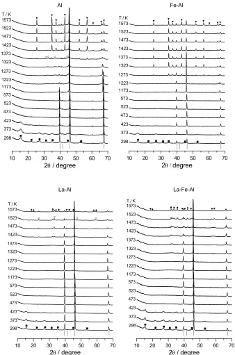
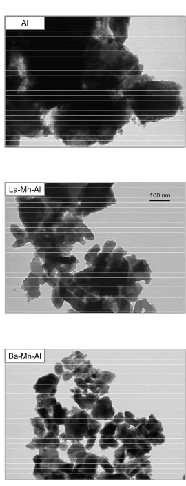
Figure 2. In situ XRD patterns during thermal decomposition of Al, Fe‐Al, La‐Al, and La‐Fe‐Al dawsonite‐type compounds. Crystalline phases: (■) AACH, (◊) ‐Al2O3, () LaAlO3, (▼) ‐Al2O3,
(♦) LaAl11O18 or LaFeAl11O19. Vertical lines indicate the position of the main reflections of the Pt
[image:31.612.132.470.77.588.2]As can be seen in the diffractograms at 298 K in (Figure 2 and 3), the XRD patterns
of the as‐synthesized samples show the characteristic reflections of ammonium
aluminium carbonate hydroxide (NH4AlCO3(OH)2, JCPDS 42‐250). The material in this
card was prepared by aging bohemite gel in a NH4HCO3 solution and was claimed to be
iso‐structural with NaAlCO3(OH)2 [32]. The patterns of our samples were
indistinguishable from those measured by Vogel et al. [31] and Groppi et al. [6]
(associated with (NH4)2Al6(CO3)3(OH)14). Accordingly, it can be concluded that the
various AACH phases reported in the literature have a very similar crystal structure,
being closely related to NH4‐dawsonite.
A marked broadening of the AACH reflections is observed in the diffractograms of
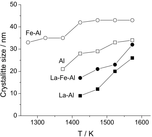
the as‐synthesized samples. The average crystallite size of the Al, Fe‐Al, and Mn‐Al
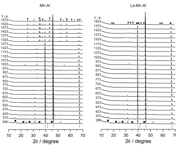
Mn-Al La-Mn-Al ■ ■ ■□ □ ■ ■ □ + + + ▼ ○ ▼ ▼ ▼○ ▼ ▼ ▼ ▼▼○ ○ ○ ■ ■ ■□ □ ■ ■ □ + ◆◆ ◆◆◆◆◆◆◆ ◆◆ ◆
10 20 30 40 50 60 70
298 1573 373 423 473 523 573 623 673 723 773 823 873 923 973 1023 1073 1123 1173 1223 1273 1323 1373 1423 1473
2 / degree
T / K 1523
10 20 30 40 50 60 70
2 / degree
298 373 423 473 523 573 623 673 723 773 823 873 923 973 1023 1073 1123 1173 1223 1273 1323 1373
1423T / K
Figure 3. In situ XRD patterns during thermal decomposition of Mn‐Al and La‐Mn‐Al dawsonite‐
type compounds. Crystalline phases: (■) AACH, (□) MnCO3, (+) Mn2O3, (▼) ‐Al2O3, (○)
MnAl2O4, (♦) LaMnAl11O19. Vertical lines indicate the position of the main reflections of the Pt
[image:32.612.129.478.285.577.2]samples was estimated by the Scherrer equation applied to the (110) reflection at 15°
2, resulting in very similar values of ca. 4 nm. Somewhat larger crystallites were
obtained in the La‐containing samples (ca. 8 nm). The occurrence of very small
dawsonite‐type crystallites in the materials has been attributed to the particular
characteristics of the applied ILDP method [18]. No additional iron‐containing phase
was present in the Fe‐Al and La‐Fe‐Al dawsonite‐type compounds, corroborating the
statement by Pitsch et al. [10] that iron is located in the lattice structure of dawsonite.
In contrast, the XRD patterns of the as‐synthesized Mn‐Al and La‐Mn‐Al samples
(Figure 3) exhibit additional reflections of MnCO3 (JCPDS 44‐1472). The average
crystallite size of this impurity was estimated to be ca. 30 nm. Groppi et al. [8,9] also
identified this phase in the precursors of La‐Mn‐Al and Ba‐Mn‐Al hexaaluminates.
As shown in Figure 4 the FT‐IR spectra of the as‐synthesized materials at 298 K
temperature exhibit the characteristic absorption bands of the hydroxyl, ammonium,
and carbonate groups in dawsonite [3,11,33]. Table 2 provides a detailed band
assignment. The absorption at 740 cm‐1, related to Al‐O vibrations in the dawsonite
structure, was observed too, being strongly overlapped with the 4 mode of the
carbonate around 750 cm‐1. Al‐O vibrations below 650 cm‐1 were not visible in the
spectra, since the in situ cell was equipped with ZnSe windows.
Table 2. Position of the bands (in cm‐1) in the infrared spectra of the dawsonite‐type
compounds.
Group Mode Al Fe‐Al Mn‐Al La‐Al La‐Fe‐Al La‐Mn‐Al
Hydroxyl 3440 3440 3444 3438 3434 3438
989 991 991 991 995 991
Ammonium 3175 3174 3176 3176 3174 3176
3055 3083 3064 3037 3033 3037
2850 2854 2858 2854 2858 2854
1832 1830 1832 1832 1832 1832
1720 1720 1720 1722 1720 1722
Carbonatea 1560 1550 1552 1564 1560 1564 1452 1452 1454 1452 1452 1452
1392 1394 1396 1394 1398 1394
1103 1103 1103 1105 1103 1105
854 854 856 852 852 852
754 754 754 754 750 750
a
Fe-Al 823 773 673 623 573 523 498 448 473 423 398 373 298 T / K
723 548 Mn-Al 823 773 673 623 573 523 498 448 473 423 398 373 298 T / K
723 548 La-Fe-Al 823 773 673 623 573 523 498 448 473 423 398 373 298 T / K
723 548 La-Mn-Al 823 773 673 623 573 523 498 448 473 423 398 373 298 T / K
723 548 500 1000 1500 2000 2500 3000 3500 4000 A bso rbanc
e / a.u
.
Wavenumber / cm-1
500 1000 1500 2000 2500 3000 3500 4000 Ab so rb an ce / a. u.
Wavenumber / cm-1
500 1000 1500 2000 2500 3000 3500 4000 A b so rban ce / a .u.
Wavenumber / cm-1
500 1000 1500 2000 2500 3000 3500 4000 A b sorban
ce / a.
u.
Wavenumber / cm-1
Al 823 773 673 623 573 523 498 448 473 423 398 373 298 T / K
723 548 La-Al 823 773 673 623 573 523 498 448 473 423 398 373 298 T / K
723 548 500 1000 1500 2000 2500 3000 3500 4000 A bs or ban ce / a. u.
Wavenumber / cm-1
500 1000 1500 2000 2500 3000 3500 4000 A bso rb an ce / a.u .
Wavenumber / cm-1
Figure 4. In situ FT‐IR spectra during thermal decomposition of the dawsonite‐type
[image:34.612.183.415.66.626.2]3.2.
Stability
of
the
AACH
phase
Figure 2 and 3 show the in situ XRD patterns obtained during thermal
decomposition of the dawsonite‐type compounds in air. The diffractograms clearly
show that reflections of the AACH phase vanished at 473 K, leading to an amorphous
phase. As shown in Figure 4, the decomposition of hydroxyl, ammonium, and
carbonate groups in the samples as monitored by infrared spectroscopy mainly occurs
in the range 498‐523 K, in good correspondence with the destruction of the mineral
structure according to XRD. The disappearance of the absorption bands of the various
species appears to be simultaneous. This is substantiated by thermogravimetric
analyses (Figure 5), presenting a one‐step weight loss in the temperature range
420‐480 K (maximum in the derivative curve at 460 K). The total weight loss amounts
to ca. 50% in all the samples. This value is very close to the theoretical weight loss of
the (NH4)2Al6(CO3)3(OH)14 formula proposed by Vogel et al. [31] (49.7%), further
supporting the chemical composition analyses discussed in the previous section. The
theoretical weight loss in the pure ammonium dawsonite NH4AlCO3(OH)2 is ca. 63%.
Further evidence for the single decomposition process of the dawsonite‐type
compounds in air was obtained by TPD‐MS. This is exemplified for the Al sample in
Figure 6. The masses associated with water, ammonia, and carbon dioxide
simultaneously evolve from the sample, displaying a maximum at 480 K. The absence
of NO and NO2 at the reactor outlet was confirmed.
Al Mn-Al La-Fe-Al
200 400 600 800 1000 1200
0 10 20 30 40 50 Weigh
t loss /
%
T / K
200 400 600 800 1000 1200
0 10 20 30 40 50 W eigh t lo ss / %
T / K
200 400 600 800 1000 1200
0 10 20 30 40 50 Wei ght lo ss / %
T / K
Figure 5. TGA‐DGT profiles during thermal decomposition of selected dawsonite‐type