Configuration Wizards and Software Product Lines-Edición
Única
Title Configuration Wizards and Software Product Lines-Edición Única
Authors Guillermo Jiménez Pérez
Affiliation ITESM
Issue Date 2003-06-01
Item type Tesis
Rights Open Access
Downloaded 18-Jan-2017 22:39:06
CONFIGURATION WIZARDS AND SOFTWARE
PRODUCT LINES
Ph.D. Dissertation by
Guillermo Jiménez Pérez
Instituto Tecnológico y de Estudios Superiores de Monterrey
Campus Monterrey
Gradúate Program in
Electronics, Computing, Information and Communications
The committee members hereby recommend this dissertation presented by Guill-ermo Jiménez Pérez to be accepted as a partial fulfillment of the requirements for
the Degree of Doctor of Philosophy with specialty in Information Systems.
Committee Members:
Dr.
ComraIttee pResident.
Dr. Don Batory. Dissertation advisor,
Dr. José Raúl Pérez Cazares.
Dr. Ramón Breña (Pinero.
Dr. David A. Garza Salazar. Director of Gradúate Program in
Acknowledgments
Conducting the research work of a doctoral dissertation takes long time. Particu-larly, this work required longer time than a "normal" dissertation may involve, because it was necessary to synchronize and coordinate work with members work-ing in different áreas and in remote locations.
First of all, I would like to thank my family Saúl, Diego, and my wife Norma, whose love provided the support I needed to remain working in such long endeavor.
I am deeply indebted to my advisor, Don Batory who dedicated extra time to conduct my research. This dissertation would not be possible without all your support.
My local advisor, José Icaza, provided me with confidence to pursue this work and remained so confident of its successful end that motivated me to keep working besides all those additional responsibilities in my work. Thank you for your encouragement.
Special thanks to my other committee members, professors Raúl Pérez, Arturo Molina, and Ramón Breña. Thank you for your insightful feedback and your interest in my work.
Table of Contents
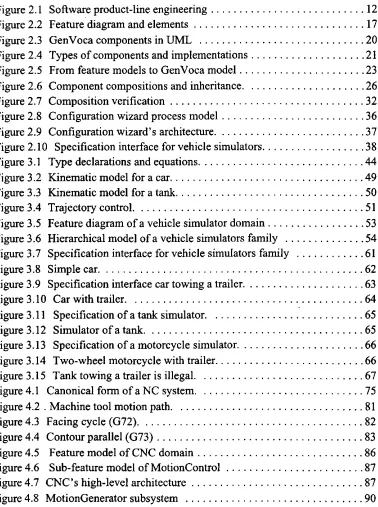
List of Figures
Abstract
The idea of software product lines is suggested to reduce both development time and cost. In search of scalable approaches for deploying large-scale software product lines, researchers and practitioners have been conducting work in several largely intertwined fields. Two áreas are component-based development and prod-uct-line architectures whose goal is that application families can be produced by integrating components as prescribed by the architecture. A third field is generator technology, whose aim is the automatic production of software from a (preferably) formal specification. A fourth technology is expert systems, developed in the arti-ficial intelligence field, which demonstrated that when knowledge in restricted domains is well-understood, it can be conveniently structured, stored, and manipu-lated thus problems can be solved by following different reasoning chains appro-priate to each particular problem, and explanations displayed to justify the resulting solution.
This dissertation shows that it is possible to define an approach that com-bines component-based development, product-line architectures, and generativo technologies to construct expert tools for automatic software production called configuration wizards. A configuration wizard is a software assistant incorporating domain-specific topological knowledge (i.e. a product-line architecture) and a library of parameterized components which can be adapted to fit in different com-positions, realizing members of a system family.
Chapter 1
Introduction
1.1 Overview and Contribution
It is well-known that constructing software from available software modules can lead to higher productivity and quality than developing software from scratch [Par79]. It has been also observed that, software modules are better reused in dif-ferent applications if they represent domain concepts [GriOOa] (i.e., features [KCH+90]). A domain is an área of knowledge or activity characterized by a set of concepts and terminology understood by practitioners in that área [BRJ98]. Domain features are useful in describing application families, which are groups of applications sharing characteristics but also exhibiting variability in their charac-teristics. In constructing application families, a set of existing and future software products can be analyzed to determine common and variable features, and a soft-ware architecture for the family can be derived, and an implementation strategy that represents this commonality in terms of a set of reusable software modules can be created [BCSOO]. An application family designed and implemented to take advantage of a common structure, common features, and prescribed variabilities is known as a software productline [WL99].
real-time versus Information systems). However, the perspective that product lines can facilitate high-quality and economic application development, has started many research efforts to identify methods, tools, and models for software product-line development, both in industry and academia [DonOO, Cha02]. As a result, different methods have been proposed to conduct product-line engineering. A common characteristic in these methods is that they are too general in the sense that almost any approach fits them (e.g. FAST [WL99]) yet others are tailored to be used in specific domains (e.g. FODAcom [VAM+98] inthe telecommunications industry).
Other research in the área of software product-lines focuses in determining what a reusable module should be and how to implement reusable modules [Par72b, ASCOO]. Two fundamental questions are how modules represent domain features, and what parameterization is necessary to allow modules to be used in different members of a product family. Answers to these questions provide guide-lines on how to represent and implement modules from which product guide-lines can be constructed.
Two complementary concepts associated to application construction in a product-line are configuration and composition. A configuration consists in the set of features and their arrangement in defining an application [SMBOO, StaOO]; the set of modules implementing a specific configuration is a composition [Bat98]. How modules can be composed to construct applications from configuration spec-ifications is determined at module design and implementation time.
wiz-lets. A wizlet is a software module specifícally designed and implemented to be composed with other wizlets using a configuration wizard as a tool to produce applications in a product line.
The specification interface of a configuration wizard displays a collection of domain features available to the application developer. A wizlet implements a feature and encapsulates semantic information describing its environmental requirements and constraints, and information describing the wizlet to the environ-ment. When executed at application composition time, a wizlet analyzes its envi-ronment to determine any inconsistencies with respect to prescribed constraints for its proper fimctioning. If constraints are satisfied, the wizlet sends the configura-tion wizard a message describing itself.
The configuration wizard collects this information to produce a description (documentation) of the application, produces the application, and compiles it into executable code. If a necessary condition for a wizlet is not satisfied, the wizlet sends the configuration wizard a message so it can reject the specification.
This dissertation presents an approach to product-line engineering based on the implementation of configuration wizards, and describes its use in constructing three different configuration wizards in three disparate domains, using different programming languages. Our approach is unique in its proposed models and tech-niques for domain analysis, domain design, and infrastructure implementation.
Concretely, the main contributions of this dissertation are:
A product-line engineering approach detailing the necessary steps to develop configuration wizards for product-lines, prescribing the work products along the process. The approach is generic thus configuration wizards can be designed and implemented to support product-line construction in different domains. Although our approach is not entirely unique in that it doesn't pro-pose a completely new model, we intégrate appropriate models for analysis (FODA's feature diagram [KCH+90]), design (GenVoca [BO92]), and implementation (configuration wizards and wizlets) for product lines. The notion of wizlets as parameterized reusable modules. Wizlets embody functionality and semantic information of how that functionality can be reused in different applications. A wizlet implements a domain feature [Esh98] and is parameterized by another wizlet (thus wizlets participate in collaborations or use case chains [JCJO93]). We show that requirements for wizlet parameterization are simple when wizlets are used as units of compo-sition, so programming languages providing basic object-oriented capabili-ties (e.g., inheritance) and encapsulation facilicapabili-ties (e.g., classes, units, modules, etc.) could be extended to support wizlet parameterization using preprocessor tools. Further, we show how programming languages can be extended to support wizlet parameterization. In contrast, other approaches for component parameterization require complex extensions to existing pro-gramming languages and complex tools for application integration (e.g., sub-jects need a subject compositor [HO93], aspects need an aspect weaver
[KLM+97, GriOOa], etc.).
automatiza-tion. In a configuration wizard, commonality is encoded as topological (architectural) knowledge, variability is used to define simple specification interfaces. Using commonality and variability in this way simplifies the implementation of configuration wizards for automatic application produc-tion. Other approaches require more complex specifications (e.g., aspects require "aspectual" decompositions and relations [KLM+97], subjects require subject descriptions and composition rules [HO93]) or don't provide hints on how to build specification interfaces for different product families. • A notation and approach to metaspecify configuration wizards, thus they can
be evolved and adapted to produce applications from different sets of requirements. How to represent, manage, and deal with variability in product Unes is an área of current research [Cha02]. Our approach is based on extending configuration wizards to implement metaconfigurators whose producís are specific configuration wizards. Instead of using a single meta-configurator to produce configuration wizards in múltiple domains and soft-ware platforms, we show how different technologies can be used to implement metaconfigurators, and present two examples of metaconfigura-tors.
1.2 Outline
from domain modeling to architectural modeling to wizlet implementation, and finally to confíguration wizards. The approach, its simplicity, and scalability are shown by presenting three configuration wizards for different domains which were implemented using different programming languages. To show how our approach to product-line engineering support evolution, we introduce the notion of metacon-figuration wizards, and present examples of how these can be useful to evolve a product-line. We present results and conclusions of our work, and fiíture research that remains to be done in the fíeld of software product Unes in general and config-uration wizards in particular. The dissertation concludes with a presentation of technologies and techniques related to software product Unes implemented as con-figuration wizards. The presentation of our work is organized as follows:
with a discussion on configuration wizards as tools for product family production and their advantage over development environments lacking semantic verification capabilities.
To demónstrate the scalability of our approach of configuration wizards, in Chapters 3-5 we describe the development of three different configuration wizards in disparate domains, implemented using different development environments and programming languages. Every chapter discusses how the implementation tech-nology used is appropriate to fulfill the requirements in each product line. First we describe each domain in detail and justify how that domain benefits from a prod-uct-line approach. We then show domain models and a brief discussion of wizlet implementation and composition for each domain. Finally, we discuss a configura-tion wizard and its capabilities in producing members of the family. These chap-ters are organized as follows.
Chapter 3 presents our first example, a configuration wizard for producing a family of autonomous vehicle simulators implemented in Java. This example is interesting in that it is simple and illustrative. It shows why Java extensions are necessary and how to proceed for implementing product lines supported by config-uration wizards. Proposed Java extensions are a simple way to extend other pro-gramming languages not supporting template-like parameterization capabilities.
Our second example, presented in Chapter 4, defines a product line of com-puter numerical control systems. This product line is characterized by real-time constraints; corresponding wizlets and configuration wizard are implemented in C++.
A third example is described in Chapter 5, which consists in a configura-tion wizard for a product line of general ledger systems implemented in Object-Oriented Pascal. Object Pascal does not support template-like parameterization, thus a language extensión mechanism, similar to that presented in Chapter 3 is implemented.
In Chapter 6 we describe how software product lines infrastructures imple-mented as configuration wizards can be evolved by constructing metaconfigura-tion wizards, whose generated applicametaconfigura-tions are configurametaconfigura-tion wizards. A notametaconfigura-tion is introduced to metaspecify configuration wizards and examples are presented describing how requirements are removed or introduced to the product line.
There are broad literature in the área of software product lines, both in methods and software technology [DonOO, Cha02]. In Chapter 7 we discuss how our work is related to that of others.
Chapter 2
Engineering Configuration Wizards
This dissertation proposes that software product lines can be constructed from pre-fabricated software modules called wizlets which are assembled by a tool called a configuration wizard. The input to a configuration wizard is a specification and the output is an application which is synthesized from wizlets that implement the spec-ification.
The general approach involves a set of activities necessary to engineer a software product-line and is commonly known as software productline engineer ing [WL99,CEOO]. In general, the engineering of product lines encompasses two steps: domain engineering and application engineering. Domain engineering activ ities produce models and infrastructures (i.e., tools) by analyzing commonality in an application family and prognosticating its variability; our approach for domain engineering is concemed with implementing configuration wizards and their accompanying wizlets. Application engineering uses domain models and infra-structures to construct different product family members [SEI01]; in our approach, application families are generated from input specifications by combining and adapting wizlets implementing the specifications.
concepts used in this dissertation. Section 2.2 presents generic steps for engineer-ing product Unes without specifically committengineer-ing to any particular notation, the idea is to set out the elements necessary to implement product-lines. Section 2.3 explains our proposed modeling notations and implementation techniques for product-line infrastructures. Section 2.4 describes configuration wizards, proposes an architecture and process for configuration wizards, and discuses its possibilities for constructing application families.
2.1 Background
A software architecture is the description of an application in terms of software modules and relations among those modules [GS93,SG96,BCK98]. An architec-ture defines the strucarchitec-ture of an application, and provides some rationale for design decisions [PW92]. The structure helps to understand how modules are intercon-nected and how every module depends on others to fulfill application require-ments.
Ideally, we would like to have a library of modules that can be used in con-structing new family members. The domain architecture is helpful in concon-structing new applications by assisting developers in selecting the appropriate module implementations. However, it would be impractical to have different module implementations for every domain characteristic. More convenient would be to define parameters thus a single module can be instantiated in different applications by providing these parameters.
The following sections describe a generic method for domain-specific architecture definition and application construction for software product-lines.
2.2 Domain Engineering
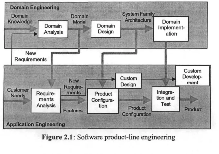
Domain engineering involves the set of activities for modeling, architecting, and implementing infrastructures necessary to produce application families. As Figure 2.1 shows, domain engineering is the first step in producing application families, and involves three activities: domain analysis, domain design, and domain irnple-mentation. These activities are described in the following sections.
2.2.1 Domain Analysis
usabil-Figure 2.1: Software product-line engineering
ity and performance, those who perform maintenance that needs an evolvable implementation, those who are in marketing needing a timely product, etc.
The first step in domain engineering consists in analyzing the similarities and differences of several applications in a domain, and talking with domain experts to gather domain commonality and variability [CSPK91]. The domain def inition determines the scope of a domain and characterizes its contents by giving examples of existing systems in the domain, counter-examples (i.e., systems out-side the domain), and generic rules and rationale of inclusión and exclusión of a given system or capability [GFD97], Once the domain has been selected, it is nec-essary to decide what belongs to it and what doesn't.
[image:25.563.98.452.129.378.2]sys-tems in a domain, semantics of the properties and domain concepts, and the depen-dencies among variable properties [JGJ97]. Domain models describe domain concepts using modeling formalisms. One particular representation of a domain model is a tree of domain features, called afeature diagram, which defines a set of reusable requirements for specifying systems in a domain by prescribing which feature combinations are meaningful, and which of them are preferred under which conditions and why [CSPK91]. Feature models represent the configuration aspect of the domain models and thus the configuration aspects of the whole reusable software. Section 2.3.1 describes feature diagrams in detail.
2.2.2 Domain Design
The second activity in domain engineering is domain design. During domain design we develop a domain-specific software architecture (i.e., a generic architec-ture) for the application family and devise a production plan for it. The architecture is defined in terms of a collection of software modules, interactions among these modules, and constraints on their interaction patterns [Tek94, GW94].
2.2.3 Domain Implementation
Domain implementation involves domain architecture, software modules, and a production plan implementation using appropriate technologies. Domain imple-mentation may involve writing developer's guides, implementing domain-specific languages and graphical user interfaces (GUI's), generators, and establishing the software production process [GK96, WL99]. Software tools are selected and the way applications will be produced is chosen and implemented. Implementation approaches have to be carefully selected by observing domain commonality and variability for different members in the application family and the available infra-structure (e.g., compilers, frameworks, etc.).
Three possibilities arise when modules are integrated to construct applica-tions. First is the case of simple domains in which modules can be (re-)used as is. For slightly complex domains, modules may require simple changes. In complex domains modules may require sophisticated adaptations to fit in particular compo-sitions [GriOOb].
Technology is not the only factor involved, domain engineers are still responsible of effective domain implementation. Elegant representations can pro-duce flexible and scalable module implementations yielding optimized compo-nents that can be combined in different ways (e.g., STL classes [MS96r], P2 components [Tho98], etc.) [BSST93, Big94, BR87]. Other approaches use more granular modules and there may be necessary to specify more complex composi-tions to construct application systems (e.g., role-based design [VN96a, VN96b, RG98]).
2.2.4 Application Engineering
The second step in a general product-line engineering approach is application engineering. Application engineering is the process of building concrete applica-tions that implement customer needs based on the domain model (see Figure 2.1). This process is supported by the infrastructures developed in domain engineering [JGJ97].
As Figure 2.1 shows, for producing new applications in the product line, requirements of the new applications have to be determined and compared to those already implemented. The result of this comparison is a set of features already present in the modules plus, possibly new requirements not yet implemented [CSPK91]. Customer requirements not found in the domain model will require custom development, new modules may need to be implemented, and even part of the design may need to be customized.
2.3 Proposed Method for Domain Engineering
conducting domain engineering that are used to develop configuration wizards. Previously we observed that our approach does not propose any new modeling notation, rather it uses models that have demonstrated their capability to represent domains.
2.3.1 Domain Modeling: Feature Models
Several different domain engineering methods have been proposed [Ara94]. They vary in how domains are represented, and how they make use of available domain architecture and application expertise. FeatureOriented Domain Analysis (FODA) is a popular domain analysis method [ KCH+90, CSPK91, GFD98, KKL+98, LKCCOO]. Its success is due to the fact that different domains can be represented and understood by a set of fearures [GriOOb]. In FODA, a feature is any distinguishable characteristic of a concept (or element) in the domain of inter-est, usually fearures are end-user visible aspects of a software system [GFD97, GriOOa]. The FODA method represents fearures using a hierarchical model called a feature diagram, indicating whether fearures are mandatory, alternative, or optional [LKK+00]. A feature diagram includes informadon of which feature com-binations are valid and which are not, and rationale for choosing or not a given fea-ture in a particular instance of the diagram. The feafea-ture diagram specifies the common and variable properties of concept instances and their interdependencies and organizes them into a coherent representation.
the features and entities in the model and a textual description of the features and entities.
Figure 2.2 shows the notation of a feature diagram and its elements. A fea-ture diagram consists of a set of nodes, a set of directed edges, and a set of edge decorations. The nodes and the edges form a tree. The root of a feature diagram denotes an application (or part of an application). The nodes in a feature diagram represent features and are referred to as feature nodes [KCH+90,Wit96,CEOO]. The edge decorations characterize features and relationships as being of different types (see Figure 2.2):
Figure 2.2 Feature diagram and elements
Optional features represent features that may be disregarded from a feature model for particular configurations. An optional feature is represented with a circle at the end of the edge linking it to another feature.
• Mandatory features must be selected in all the configurations of the feature model. They represent the commonality among different model instances. A mandatory feature composed exclusively of optional features means that at least one of them has to be selected in all configurations (i.e., applications). No special edge decoration characterizes this type of feature.
• Composedof relationships express features that are composed of several sub-features, following a decomposition/aggregation abstraction mecha-nism. This relationship is represented by drawing a line from the super-fea-tures to each of its sub-feasuper-fea-tures. No edge decoration is required for this representation.
• Generalization/specialization relationships represent abstract concepts that can be concretized (i.e., specialized) in several ways. A generalization rela-tionships is represented by a diamond at the generic's feature end. A line is drawn to each available specialization feature from the diamond. Generali-zations are substitutable by one or more of their specialization features. • Constraint relationships represent requires or mutual exclusión constraints.
These semantic constraints are defined on operational features and variants, to give the model consistency. A dashed line may interconnect two features indicating that one requires the presence of the other in the model. Mutual exclusión is specified by an are joining mutually exclusive features. Addi-tionally, incompatibility in the choice of two features can be expressed as sepárate relationships with respect to the diagram, or using requires features or excludes features attributes (i.e., labels) in the relationships.
The notation used to specify feature models is exemplified by Figure 2.2 which shows thst:f0 is the higher level domain feature (which can be an
applica-tion or subsystem). An applicaapplica-tion should always contain feature f¡ and one of f2
the featuresy};,/^, andfJ3. Feature/2 is specialized by features/^;,^ <
is a generic feature. Feature/j has a meaning similar to that of/}. Finally, the pres-ence off2j in a feature model, requires the presence of/}j in the model (however,
the presence of 136 doesn't require thaty^ be present).
2.3.2 Domain Design: GenVoca
GenVoca [BO92] is a domain-independent model for designing application fami-lies. Applications are modeled as hierarchical compositions of layers. GenVoca layers can be considered functionally as representing either refinements or exten-sions. A refinement or extensión adds data and operations to the input to produce the output; each layer contains a number of object classes and the layer below extends the layer above it by adding new classes, or adding new methods and attributes to existing classes [Sin96, Sma99].
Each GenVoca layer implements a type, represented by its interface (that is, the set of services it offers to its higher-level layer). Additionally, every layer (except the layer at the bottom) is dependent upon a lower level layer implement-ing a type. Each layer declares the type it implements (the implemented type or simply its type) and the type it requires (the required type) its lower-level layer to implement. Layers are implemented as software modules (generically known as components in GenVoca). A GenVoca component encapsulates a suite of interre-lated fimctions, variables, and classes that work together as a unit to implement a particular feature [Tho98] (i.e., in GenVoca features are types, thus there may be several implementations of a feature). Different components can implement the same type (i.e., layer defínition), thus becoming interchangeable.
_;•„ i i component
r—O (j
—o interface/type dependency
Figure 2.3 GenVoca components in UML
2.3. This representation shows that a GenVoca component is a particular imple-mentation of a type. In Figure 2.3 upper-case letters represent types, and lower-case letters represent components (type implementations). The dotted lines in Fig-ure 2.3 represent the dependency of a layer/component from the lower-level layer / component (type) that is required by a component. Note that dependency is on the type, which means that any component implementing that type can be used as an actual parameter.
The similarities and differences among members of a family are exposed by comparing the component compositions that define them. A number of genera-tors for product lines have been based on the GenVoca model (Génesis [Bat88] a compositional generator for a datábase product line, P2 [Tho98] C-based transfor-mational generator for a data structures product line, P++ [Sin96] a C++-based compositional generator for a data structures product line, and DiSTiL [SB97] a Java-based transformational generator of a data structures product line). An impor-tant result from GenVoca product line implementations was the realization that the number of fundamental domain abstractions is typically rather small, but many dif-ferent implementations are possible for every abstraction [BSST93].
R = {a, b, c}
S = {d(x:R), e(x:R), f(x:R) }
T = {n(x:T),m(x:T),p,q(S)}
Figure 2.4 Types of components and implementations
(components d, e, f), and type T has four implementations (components n, m, p,
Q).
Each component of type R is distinct (i.e., it encapsulates its own algo-rithms, has its own unique performance characteristics, has its own unique mem-ory footprint, etc.). All components of R implement the same type and thus are plug-compatible. The same holds for S and T. Note on Figure 2.4 that a parameter denotes the type of a required component.
An application is a named composition of components called a composi tion equation. Component composition is accomplished by instantiating compo-nent parameters. For example, consider the following three composition equations (components corresponding to Figure 2.4):
appl =d(b); app2 = d(a );
app3 = f( a );
Application appl composes components d with b, app2 composes d with a, app3 composes f with a. All three applications are composition equations of type S (because their outermost components implement type S). This means that appl, app2, and app3 are interchangeable implementations of S.
means that compositions n(m(p)) and m(n(p)) are possible. In general, the order in which symmetric components are composed matters.
Syntactic compatibility between components is easily checked by verifying that for each component the type implemented by its actual parameter corresponds with its required parameter type. Thus app7 is syntactically valid, because b's implemented type and cfs required type are both of type R.
Component semantic compatibility is more complicated. Note that some combinations of components may be syntactically but not semantically correct. That is, each pair of components in the application requires and implements com-patible types, but the resulting algorithms may be invalid for some reason. To ver-ify the semantic correctness of an application, each component must supply domain-specific information that describes the assumptions and constraints for using that component [BG97]. Such information can be handled by a generator to verify semantic correctness. Later in this chapter we describe how semantic verifi-cation is dealt with.
2.3.3 Translating Feature Models to GenVoca Models
Up to this point we have presented two modeling notations. Feature diagrams to describe domain entities of interest, and GenVoca for designing product Unes. However, we haven't explained how GenVoca designs can be obtained from a fea-ture diagram. In this section we describe the process to map feafea-ture diagrams to GenVoca designs.
(a) (b) (c) (d)
Figure 2.5 From feature models to GenVoca model
design described by Figure 2.5(b). Note that an annotation symbol in Figure 2.5(b) describe optional and generic components2.
In transforming feature diagrams to design diagrams, one should acknowl-edge that a feature diagram shows how features are related in a structural way, the hierarchical diagram will show how features are related at execution time. Features can be abstracted into individual design entities. These design entities consist of groups of interacting classes (thus they can be interpreted as patterns in a design pattern approach [GHJV94], collaborations in a collaboration-oriented approach [VN96, SB98], role-models in role-based design [RG98], subjects in a subject-ori-ented approach [OH92], etc.). Each design entity is a GenVoca component (or more appropriately, a layer, because a single feature can have múltiple implemen-tations).
The root feature in a feature diagram will be the layer at the top in the hier-archy. How the other features map to the hierarchical model requires analyzing how features relate to one another at application execution time. For instance, let's say that for the feature model in Figure 2.5(a), feature y? may use the functionality (i.e., classes, methods, and attributes) from feature/?, and/2 may use the
ality provided by f4 (when present, since f4 is optional), and finally that f3 pro-vides the lower-level functionality for the application. This analysis produces Figure 2.5(b). Note that different feature interactions produce different hierarchical models. However, application families are characterized by their features and their interactions, thus application families are in fact described by hierarchical models obtained from feature models.
Note that Figure 2.5(b) doesn't include features f31 and/32. The reason is that both are specializations of feature/?, and they will be used when the specific characteristics they define are needed. Note also in Figure 2.5(b) that f3 is never used, but instead one of its specializations, f31 or f32. Figure 2.5(c) shows an instance of the composition for an application implementing features//,/2,/¥, and f31; another application which implements features//,/?, and/32 is depicted by
Figure 2.5(d).
The annotations used in Figure 2.5(b) use symbols similar to that used in a feature diagram to emphasize optionality (a circle) and selection (a diamond). These conventions help to keep consistency in the interpretation of diagrams used to construct product line infrastructures.
Feature diagrams have been broadly used in domain modeling and differ-ent mappings to design differ-entities are suggested. For instance, feature diagrams can be translated to reference architectures [KKL+98] and object diagrams [LKCCOO, GFD98, GFD97]. Our selection of translating feature diagrams to GenVoca is based on the fact that GenVoca diagrams represent product-line architectures and thus can be used to implement product lines[Bat98].
2.3.4 Domain Implementation: Wizlets as Components
approach must express domain commonality and variability, thus commonality can be exploited in different applications and components can be adapted to meet domain variability.
Another aspect of architecture implementation is domain evolution [Bos99]. The implementation approach should provide support to evolve as domains evolve [ML98, RJ97], because by clearly reflecting the product Une architecture, the implementation simplify evolution [Par79, VN96b, Sma99].
In particular, an approach for implementing GenVoca models should reflect hierarchical component stacking. It should allow module composition in a linear stacking, and should support component swapping inherent in GenVoca models. An implementation approach that has shown to be adequate for implementing GenVoca models is that proposed by Smaragdakis and Batory [SB98], which has its roots on the work by VanHilst [VN96a,VN96b], and Bracha and Cook [BC90]. The basic technique implements every component as a mixin class. Mixins (also commonly known as abstract subclasses [BC90]) represent a mechanism for spec-ifying classes that will eventually inherit from a superclass. This superclass, how-ever, is not specified at the site of the mixin's definition. Thus a single mixin can be instantiated with different superclasses yielding widely varying classes. This property of mixins makes them appropriate for defining uniform incremental extensions for a multitude of superclasses. When a mixin is instantiated with one of these superclass, it produces a class extended with the additional behavior.
A wizlet is a mixin encapsulating a group of related classes, instead of a single class3. Wizlets may use programming language extensions in their
]-oP
(a) (c)
Figure 2.6: Component compositions and inheritance.
compositions [Bat98]). First, Figure 2.6a is a reproduction of the component com-position presented on Figure 2.3. Figure 2.6b shows an inheritance hierarchy equivalent to composition on Figure 2.6a. Note that class x is the top class in the hierarchy, which corresponds to the lower-level component in Figure 2.6a. The following class in the hierarchy (in Figure 2.6c) is h, which corresponds to the
layer on top of layer x (in Figure 2.6a). Proceeding in that way we reach the top level of the layer hierarchy and the bottom level of the inheritance hierarchy. While this notation and correspondence seems strange, it is due to historical rea-sons. That is, in general the ordering of a class hierarchy is the inverse of the order of a layer hierarchy.
Note in Figure 2.6b how every class/wizlet extends its super class by add-ing ftmctionality to an inner class in its superclass, or addadd-ing several new inner classes. Inner classes that are not extended by a lower level class are final classes.
Thus, when wizlets are composed, a forest of inheritance hierarchies is created. Adding a new wizlet (stacking a new layer) causes the forest to get progressively broader and deeper. It is through the use of inheritance that new operations/meth-ods can be added to múltiple application classes merely by plugging in a compo-nent [Edw95].
Figure 2.6c unirles the representation for components as types and classes, that is, every wizlet implements a type and is meant to inherit a super-wizlet imple-menting a type. The actual super-wizlet is not known at wizlet implementation time, so its specified as a type.
Wizlets can be easily implemented in C++ using parameterized inherit-ance. In this case, a wizlet is a parameterized class with the parameter becoming its superclass4. Using C++ syntax we can write a wizlet as:
témplate class <class WizletSuper> class Wizlet : public WizletSuper {
public:
class InnerClassl:
public WizletSuper::InnerClassl { ... };
class InnerClass2:
public WizletSuper::InnerClass2
Here Wizlet is the abstract subclass being defined, and WizletSuper is a parameter defming Wizlet's superclass.
Wizlets are composed by instantiating one wizlet with another as its param-eter. The wizlets are then linked as a parent-child pair in the inheritance hierarchy. C++ provides a direct mechanism for expressing wizlet compositions, for instance:
typedef wl< w2< . . . < w n > . . . > > C (2.1)
is a témplate composition where wl, w2, ..., wf are wizlets, "<...>" is the C++ operator for témplate instantiation, and C is the ñame given to the class that is pro-duced by this composition5 .
Composition (2.1) has a direct counterpart in GenVoca, (2.1) has the exact form used in GenVoca for composition equations, except for syntax ( "(..)" replaces "<...>"). Thus, (2.1) corresponds to equation (2.2):
C = wl (w2 ( ... ( wn ) ... ) ( 2 . 2 )
where wl,... are wizlets representing GenVoca components.
This section described how wizlets (GenVoca components) are imple-mented by parameterized classes, showing implementation code in C++, because C++ directly supports class parameterization. We demónstrate in following chap-ters how other object-oriented programming languages supporting inner class encapsulation, but not necessarily class parameterization can be extended to sup-port class-like parameterization. As examples, subsequent chapters describe how Object-Oriented Pascal and Java can be extended to implement GenVoca compo-nents.
2.3.5 Composition Validation
Having components correctly implemented doesn't imply that all their combina-tions define valid applicacombina-tions. A fundamental problem for all component-based software development technologies is whether component compositions are con-sistent/valid [BG97, DP98, Szy98].
The implementation of automatic composition validation of hierarchical component compositions requires representing the properties that components add and need from their environment using configuration predicates. Configuration predícales describe a component to its environment and prescribe properties that
should be met for that component to participate in a composition.
Configuration predicates can be of three types: assertions, boolean or numeric.
• Numeric: this type of predícate can provide information concerning the com-ponent algorithmic implementation such as its algorithmic complexity or memory requirements. Other predicates may define actual parameters declar-ing component properties such as máximum number of elements allowed in a data structure; valúes distinguishing the component, such as the numbers of wheels in a vehicle being simulated by the resulting application, number of axes along which a cutting tool can move in the machine tool that will be con-trolled by the resulting application, etc.
• Assertions: assert an important property of the component, such as declaring the presence of the component in a composition. Assertions are similar to numeric predicates but the assessed values are boolean in nature. Note that assertions are a special kind of boolean expression whose value is set to true when a component is found in a composition.
Configuration predicates can be additionally characterized as being of four types: pre-conditions, post-conditions, post-restrictions and pre-restrictions; such classification depends on where properties defined by predicates are used to verify composition validity. To discuss configuration predicate types, suppose the gen-eral case in which k is a component:
• Postconditions: Post-conditions are properties of k that are exported to layers beneath k in a component composition.
• Precondition: Pre-conditions define properties that must hold for components to work properly; they test the cumulative post-conditions of layers that lie above k in a composition. It is common to have components whose pre-condi-tions and obligapre-condi-tions are not satisfied locally (i.e., by components that are not adjacent in a composition equation).
• Postrestrictions: are properties of k that are exported to layers above k in a composition.
• Prerestrictions: (also known as obligations) are pre-conditions for instantiat-ing layer parameters; they test the cumulative post-restrictions of layers that lie beneath k in a composition.
Two commonly used boolean predícate types are (note that these can be further characterized as being of one of the four types described):
• Requires: specifies that a component of particular type and/or supporting cer-tain specifíc characteristics is required below or on top of the current compo-nent being verified.
• Prohibits: the presence of a particular component type or properties defined by other components are not allowed in the composition.
Given configuraron equations representing component compositions, con-figuration validation involves:
A top-down propagation of post-conditions, and the testing of component pre-conditions, and
• A bottom-up propagation of post-restrictions and the testing of parameter pre-restrictions.
To implement configuration validation, configuration equations can be encoded in different ways in programming languages. To propágate configuration state up and down the component hierarchy, configuration state can be maintained in a sepárate state component. Every time the validity of a component in a compo-sition needs to be verified, the environment information discovered up to the moment can be extracted from that state component. For instance, in an object-ori-ented programming language, an object may store environmental information as attribute valúes of a composition. Every object implementing the validation can receive such state object as a parameter, and retrieve and store state attributes which can be of interest to other components.
A I
B i C i D
<. •>
f «i
f *»
í ^
S t a t e
Figure 2.7 Composition verification
Inside every component, the validation code is the code that asserts the Information of the component, or the code that verifies or prevenís the presence of other components. The following code fragments exemplify each of these types, in the example prefix state represents an instance of the State component, and component would be represented by the component ñame whose predícales are being defined:
Assertion: For components that need to assert its presence or properties to other components (for instance, the following code, component can be substi-tuted by stepMotor if a stepper motor is being used in a composition):
state.componentSet = true; state.someProperty = 2;
Requires: in the code that follows, the word reguiredComponent would be replaced by a corresponding component ñame6:
if( ! state.requiredComponentSet)
error("Component needs a reguiredComponent in the composition") if( state.numAxis != this->numAxis)
error("Number of axis in Component doesn't match the defined number of axis")
Prohibits: In the following code, the identifier prohibítedComponent
would be replaced by a component ñame:
if( state.prohibítedComponentSet)
error("prohibítedComponent can't be used in combination with Component")
The previous code fragments show how explanation code is included together with verifícation code. Such information can be extremely useful at appli-cation configuraron time, for producing well defmed appliappli-cations.
Depending on how components are planned to be composed to build appli-cations, and facilities in the development environment, validation expressions (i.e., configuration predicates) can be implemented together with application code inside a single component, or the implementation be split in one application com
ponent (containing the code a component adds to the application) and a
counter-part verifícation component (containing the code implementing the configuration
predicates for that component). We can justify the separation of code based on how both parts are used. Verification code is executed only once in the life span of an application (to verify the validity of a component composition specifying the application), however the application code will be executed (potentially) many times. Note that such separation of implementation is suggested for cases in which components are to be integrated in a compositional way, instead of in a transfor-mational way. Generative components may contain both the generative code and the validation code inside a single component, because both parts are executed at generation time.
implementa-tion for wizlets: a ftmcimplementa-tional (applicaimplementa-tion) part, and a validaimplementa-tion part. (or stated another way, the verification code is evaluated statically at configuration time, while application code is evaluated dynamically at application runtime).
2.4 Configuration Wizards
The synergistic combination of feature models with GenVoca hierarchical product-line architectures and parametrized wizlets sets the foundation for imple-menting product Unes. However, there are limitations for the broad applicability of the implementation approach described earlier. The module/class parameterization mechanism is fundamental for implementing components as parameterized classes. However, mainstream object-oriented programming languages in use today do not provide support for class parameterization7.
In general, compilers offer limited support needed at product-line applica-tion-engineering time (i.e., composition time). In the presence of a syntax error, it would be convenient that compilers provide developers with hints on what is caus-ing errors. A similar situation occurs for the more sophisticated need of composi-tion verificacomposi-tion (i.e. valídate that components in the composicomposi-tion precisely define an application). Although it is possible to implement limited composition consis-tency validation by type declarations in the class hierarchies [Sma98], industrial level application systems require more complex configuration predicates than can be implemented in one direction (top to bottom).
Unfortunately, even programming languages supporting parameterization capabilities offer limited support for composition verification (syntactic and semantic). For instance, C++ compilers produce large and intimidating messages
for syntactic errors in the presence of erroneous témplate compositions . Compo-nent compositions producing syntax error messages are difficult to debug. If a developer is unfamiliar with the nuts and bolts of component implementation for the domain at hand, it is a monumental work to find error sources. Although con-figuration predicates provide the developer with support for dealing with semanti-cally incorrect compositions, it is a difficult endeavor to manually verify that compositions don't viólate any predícate.
Syntax errors are unavoidable, but they occur at component development time (i.e., component developers will solve them when implementing compo-nents). It is at application engineering time (i.e., when constructing members of the application family) that semantic verifícation will be of great help for the applica-tion developer.
We argüe that application engineering in a product-line environment can be simplified by the use of configuration wizards. Configuration wizards are software tools containing wizlets as components, predicates prescribing valid compositions, a specification interface, and a generator.
Figure 2.9 depicts our proposed generic architecture for a configuration wizard. Figure shows how the two parts in which we divided wizlets, are stored in two different containers: a wizlet repository storing the application code part, and the domain knowledge repository containing the verifícation part of wizlets (i.e., the topological information of the product-line architecture and configuration information prescribing valid wizlet compositions). A specification interface offers the application developer editing facilities to specify the application at hand9. The generatorreceives application specifications from the developer,
component syntax tree
Generator ^ Verífier
Figure 2.8: Configuration wizard process model
lates them to concise representations (i.e., layer stacking), verifies their semantic correctness and generales the application by adapting wizlets implementing speci-fied requirements.
Process models helps to describe how a sequence of steps (i.e., transforma-tions) produce a final result. A process model describing involved steps and inter-medíate results between steps in a configuration wizard, is shown in Figure 2.8. The process model Figure 2.8 shows that a configuration interface is used for requirement specification, the result is an application specification, consisting in the required features specified by a developer. Speclnterface allows specifying only non-mandatory features. The requirements set is the input to the eqBuilder module, which transíales specifications lo equivalenl composition equations. The composilion equalion produced by eqBuilder includes elemenls representing man-datory domain features inserted al appropriale posilions (as defined by the prod-ucl-line architecture).
The next module in the process is Parser, whose task is to build a syntax tree from the composition equation10. After that, a Verifier module checks (by
evaluating configuration predicates) that the syntax tree corresponds to a valid wizlet composition. Finally, the Generator module parses the syntax tree to instan-tiate wizlet parameters and produce any extra information necessary thus the gen-erated application can be compiled.
Along the configuration and generation process, modules are informing the user/developer of the progression by sending messages to a message handler.
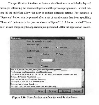
Specification interfaces could be designed very differently for different domains and product lines. What we affirm is that specification interfaces can facilitate requirement specification by explicitly presenting domain features (types) and their specializations (different implementations). For instance, Figure 2.10 shows a possible specification interface for a product-line of vehicle simula-tors11. In the example, specializations are grouped using different grouping
facili-wizlet repository
specification interface
^ ^
generator ww
i 1
application
JJ
domain knowlede
Figure 2.9: Configuration wizard's architecture.
lO.Complex domains may have layer representations consisting in branches thus needing parse trees for their analysis [BCGS95].
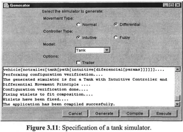
ties (as available in the development environment). For instance, movement types are in a group called "Movement type" whose cholees are "Normal" and "Differ-ential"; "Controller type" grouping include specializations "Intuitive" and "Fuzzy"; "Model" defines a list of vehicle types the developer can choose from; finally, there is a single "Option" to speciíy if the vehicle is towing a "Trailer" or not.
The specification interface includes a visualization área which displays all messages informing the user/developer about the process progression. Several but-tons in the interface allow the user to initiate different actions. For instance, a "Genérate" button can be pressed after a set of requirements has been specified; "Genérate" button starts the process shown in Figure 2.10. A button labeled "Com-pile" allows compiling the application just generated. After the application is
com-re Generator
Select the simulatorto genérate:
Movement Type:
& Normal C Differential
Controller Type:
<? Intuitive (~ Fuzzy Model:
13
Optlons:
l~ Traller
vehicle[notrailer[car[path[intuitive[normal[params]]]]]]....
Performing configuration verification....
The generated simulator is for & Car with Intuitive Controller and íormal Movement Principie ....
^onfiguration verification done.... Fixing wizlets to f it composición.... Hizlets have been fixed....
fhe application has been compiled succesfully.
(
I I .„„ ... „_.,_...! I [image:51.568.84.498.225.668.2]Genérate [|| ..Cpjñplle^J| Execute
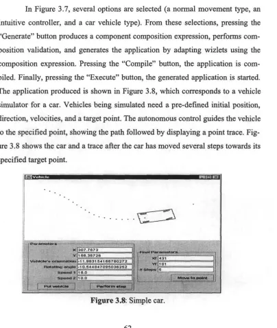
piled, it can be executed directly from the configuration wizard using the "Execute" button.
By integrating a suite of validation and generator tools inside configuration wizards, we substantially enhance the individual capabilities and effectiveness of these tools. Incorporating domain knowledge in the way of configuration predi-cates may offer expert guidance to application developers so that design blunders can be avoided. With the assistance of configuration wizards, non-domain experts would consistently produce high-quality designs (i.e., configuration wizards can critique specifications so designs can be improved).
2.5 Recap
This chapter presented the general concepts related to software product-line engi-neering and proposed a method based on the consistent use of feature modeling for domain modeling, GenVoca as the architectural framework to describe product-lines as hierarchical organizations of plug compatible components called wizlets, a systematic approach for wizlet implementation using module parameterization (classes for C++ in particular), and finally, explained our thesis that a configura-tion wizard can be used to genérate applicaconfigura-tions in product families.
We proposed that software product lines can be implemented as configura-tion wizards which:
• Free application engineers from manually building composition equations (i.e., component compositions). Wizards help to construct composition equations from input specifications using a product-line architecture.
• Free application engineers from knowing programming language composi-tion syntax to construct composicomposi-tions.
The next chapters demónstrate how configuration wizards can help to con-struct software product-lines in different domains using different implementation technologies. Three different product lines will be shown: a simulator for autono-mous vehicles, a computer numerical control system, and a general ledger for credit unions. Each product line will be implemented using a different program-ming language, thus helping us to identify programprogram-ming language extensions nec-essary for implementing configuration wizards for product lines in different environments.
Our goal is to demónstrate that confíguration tools with limited generative capabilities, supported by programming languages providing encapsulation and inheritance mechanisms, are enough to implement product lines.
Chapter 3
Vehicle Simulators ProductLine
We present our first example of a configuration wizard implementing a software product-line in this chapter. The example consists of a family of software simula-tors for autonomous vehicles having two, three, and four wheels. The example is interesting in that it shows in detail the application of our proposed method for product-line engineering. The configuration wizard and parameterized compo-nents are implemented using Java as programming language. As Java does not directly supports class parameterization, we extend it to allow wizlets (necessary for a configuration wizard) to be defined as parameterized classes.
3.1 Autonomous vehicle simulation
constructed due to a combination of the aforementioned reasons. Having compo-nents of the family implemented in software would simplify the construction of different simulators by composing components that implement the required fea-tures.
The Research Laboratory of the Artificial Intelligence Center at ITESM was interested in analyzing different algorithms for autonomous vehicle control, to experiment how vehicles move to reach a predefined target point from an arbitrary initial position and direction. It was expensive and time consuming to perform all modifications and implement the corresponding algorithms in real vehicles to ana-lyze their behavior. One problem is that vehicles with different shapes and sizes behave differently for similar control algorithms. For instance, two-wheels vehi-cles behave very differently from four-wheels vehivehi-cles, thus the necessity of hav-ing different movement algorithms for different types of vehicles.
The goal of our simulators product-line is to allow researchers to specify simulators incorporating a desired set of fearures for a vehicle and to build the cor-responding simulator from that specification. Once constructed, the simulator can be used in analyzing the path followed by the corresponding vehicle for a particu-lar algorithm. Among the features a researcher may want to specify are: the vehicle type (e.g., motorcycle or car), the vehicle tows a trailer, use a specific movement algorithm, etc. Simulators should provide researchers with user-friendly interfaces to allow them perform different specifications within a given simulator (e.g., initial orientation, path to be followed, speed, etc.).
traces, not the time vehicles take to traverse predefined paths. Given these require-ments, Java was selected as programming language.
3.2 Static Parameterization in Java
The analysis presented in the previous section justifies the selection of the Java programming language as a good candidate to satisfy simulator family require-ments. However, our approach for wizlet implementation presented in Section 2.3.4 is restricted to programming languages supporting class-like parameteriza-tion mechanisms (e.g., C++ témplales), and Java doesn't directly supports class parameterization. Still, a cióse analysis to wizlet parameterization and Java capa-bilities reveáis that the only extra support necessitated in Java is to allow classes as parameters1. In the following paragraphs we show how Java can be extended to support parameterization for class composition by inheritance, when super classes are unknown at class implementation time.
There are several proposals for extending the Java programming language with template-like parameterization [BOSW98, AFM97, MBL97]. However, to keep consistency in the way we express component compositions across program-ming languages, we preferred an ad-hoc and simple extensión to Java, instead of using one of these extensión proposals. Our proposed extensión has similar syntax to that of GJ [BOSW98], however, the similarity ends there, since we don't offer full support for generic types, as GJ does.
We extend Java syntax to implement wizlets as parameterized classes, thus the syntax in Java is similar to that explained in the previous chapter for C++. In
the extended syntax, Java classes can be parameterized by declaring its super wiz-let as a parameter, as foliows2:
class Wizlet extends «WizletSuper» {
public class Innerl extends «WizletSuper». Innerl
(...)
public class Inner2 extends «WizletSuper». Inner2
(...)
Similarly to what we did in C++3, class Wizlet is an abstract subclass,
and WizletSuper is a parameter defining Wizlet's superclass. Java's class encapsulation is similar to C++'s, thus the similarities between C++ templates and our proposed Java extensión. In Java, wizlets encapsulate several inner classes, and Java's inner classes are inherited, just like they are in C++. Thus Java's wizlet implementation is performed using parameterized inheritance and nested classes, just like we can do in C++. Let's see how this mechanism works in a simple wizlet
implementation example.
Suppose type declarations in Figure 3.1 (a) describing type Device whose specialization components are Window and Printer, and type R whose only
compo-Window Device={ Window, Printer}
Report
R = {Reportf X:Device) } a1=R9port(W,ndow) a2=Report( Printer)
(a) (b) (c)
Figure 3.1: Type declarations and equations.
2. Note our use of «..»to represent class parameters, which is not native Java syntax.
nent is Report. From declarations in Figure 3.1 (a), one can construct two composi-tions. One is shown in Figure 3.1(b) describing an application where Report senas its output to Window. The other component composition is shown in Figure 3.1(c) which describes an application where Report component sends its output to a Printer component. In all cases that follows, we assume that wizlet components contain two inner classes Innerl and Inner2, which they extend. The following is a partial Java implementation of the Report component using our proposed exten-sión to Java:
class Report extends «WizletSuper» {
public class Innerl extends «WizletSuper». Innerl { ... }
public class Inner2 extends «WizletSuper». Inner2
For simplicity, we maintained the internal definition of Report similar to our implementation code shown earlier for a parameterized Java class, changing the wizlet ñame only (i.e., from Wizlet to Report).
To show how proposed Java's extensión mechanism works, lets implement Window and Printer components. The code for Window is:
class Window {
public class Innerl { ... } public class Inner2 { ... }
where Innerl and Inner2 represent classes internal to Window.
cíaos Printer {
public class Innerl { . . . } public class Inner2 { . . . }
From these implementations, we can speciíy composition equations defin-ing systems that display a report inside a window (see Figure 3.1(b)) on the moni-tor screen, or that print the report on paper (see Figure 3.1(c)). Note, however, that the implementation of Report cannot be directly compiled in Java (i.e. the wizlet from which Report inherits has to be concrete in the code implementing Report). We can adapt parameterized wizlets using composition equations. From Figure 3.1(b) we substitute4 the parameter WizIetSuper with Window (as declared by
composition equation in Figure 3.1(b)) in the extended Java code. The resulting code for Report is:
class Report extends Window {
public class Innerl extends Window.Innerl { ... )
public class Inner2 extends Window.Inner2
(...)
}
Similarly, the concrete code obtained from Figure 3.1(c) using correspond-ing wizlets (i.e., Report and Printer) is:
class Report extends Printer {
public class Innerl extends Printer. Innerl { ... }
public class Inner2 extends Printer.Inner2
These examples show how, even though Java doesn't offer compiler sup-port to construct component compositions (similar to C++'s témplate expressions), we still are able to manually adapt components to fit particular compositions. Using this approach, a simple text editor can be used to adapt wizlets, thus they can be compiled into applications. Obviously such manual approach is undesirable and error prone (there is always the risk that incorrect substitutions are made, such as characters deleted by mistake, thus semantically or syntactically incorrect com-positions are created).
A better approach is to make use of information about how components need to be adapted (such information is obtained from a wizlet composition expression specifying an application) so a preprocessor can parse equations and perform necessary adaptations to each wizlet. The resulting pre-processed compo-nents can now be compiled into an application by the standard Java compiler. Because pre-processing only makes sense after we can guarantee a semantically correct composition expression, configuration predicate checking and wizlet pre-processing should be integrated into a single tool. To opérate, such tool needs as input the composition specification (i.e., a composition equation) for an applica-tion, and produce the Java source code for that application.
3.3 Domain Model for Autonomous Vehicles
As described earlier in this chapter, the domain includes applications to simúlate the operation of vehicles. Vehicles can be of different types5 (e.g., Car,
Two-wheels motorcycle, Three-wheels motorcycle, Tank, etc.), implement differ-ent movement principie (normal or differential, which are explained later), and dif-ferent control algorithms (intuitive and fuzzy, explained later). For performing a simulation, users provide initial valúes for parameters describing initial conditions for a given vehicle (e.g., direction the vehicle is facing, constant speed, initial posi-tion, etc.), and define a path the vehicle should follow (such path may consist in a single target position or a sequence of points).
The common operations that vehicle simulators need to implement are: • Put vehicle. A given coordinate point defines vehicle's initial position. An
angle states the direction a vehicle is facing.
• Move to point. Move towards a predefined point (performing the necessary direction adjustments if destination point is not in front of vehicle),
• Follow a path. A path is defined by a set of points. The vehicle must follow the trajectory defined by the path.
The way vehicles opérate is determined by their kinematic models. The fol-lowing are canonical kinematic models for different types of vehicles we are inter-ested in simulating.
3.3.1 Kinematic Model of a Car
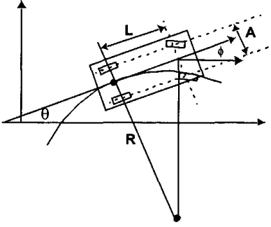
The kinematic model typical of a car (Figure 3.2) is one in which back wheels are fixed to an axis and front wheels can be turned right or left [Lat93, DJOO].
9 = Car's angle from the horizontal axis in the plañe. (j) = Tires's angle with respect to car axis (car inclination). L = Distance between front and rear wheels (length).
A = Distance separating wheels in a given car's axis (width). R = Current turning radius.
A car's referencepoint is the center of rear axis, it represents the car's posi-tion. A car's movement principie depends on where locomotion power is applied. If locomotion power is applied at the rear wheels (called differentialprincipié), the velocity of the wheels need to be controlled. If locomotion power is applied at the front wheels (called normal principié), rear wheels' velocity is irrelevant.
A car's kinematic model can be translated to an equivalent model for a two-wheel motorcycle. For a motorcycle, we can imagine both wheels in a given axis (frontal or rear) collapsing into a single wheel at the middle point in that axis. In a two-wheel motorcycle, drive control is in the front wheel, while rear wheel cannot turn. Thus we don't need any special consideration of how a two-wheel motorcycle should be controlled, the only difference is that A (distance between wheels in the same axis) is equal to zero.
[image:62.614.208.402.469.631.2]