EFFECT OF THE POROUS MEDIA TRANSVERSE ISOTROPY OND SOUND
TRANSMISSION PROPERTIES OF DOUBLE WALL SYSTEMS
PACS REFERENCE: 43.55.Rg
TRAN-VAN J.(1,2); OLNY X.(2) ;and SGARD F (2). (1) Saint-Gobain Isover France
"Les Miroirs"
92096 La Défense cedex France
+(33) 1 47 62 42 78 +(33) 1 47 62 42 15
[email protected]
(2) Laboratoire des Sciences de l'Habitat, Département Génie Civil et Bâtiment, URA CNRS 1652, Ecole Nationale des Travaux Publics de l'Etat
rue Maurice Audin
69518 Vaulx-en-Velin Cedex +(33) 4 72 04 70 31
+(33) 4 72 04 70 41
[email protected]
,[email protected]
ABSTRACT: Most of models used to predict the sound insulation performance of multilayered structures, including a porous material, assumed it to be isotropic.
The aim of this paper is to study the transverse anisotropy of porous media like glass wool on transmission loss performance. The porous material is modeled using Allard's1 equations. A numerical model based on a transfer matrix approach is developed to predict the transmission loss of a double wall made up of two elastic plates separated by a cavity filled with mineral wool. Comparison between anisotropic and isotropic approach are carried out in order to assess the importance of anisotropy on the acoustics characteristics of the system.
INTRODUCTION
Anisotropic porous media, such as rock wools or glass wools, are commonly used in building engineering for their acoustic properties. They can be utilized in sound insulation systems (mass-spring-mass systems) or as absorbing panels. Most of these materials present a specific structure composed of fibers plans superposed one to each other. These anisotropic structures are called transverse isotropy. So, these media present two characteristic dimensions, one planar and the other normal to the fibers planes.
1. THEORY
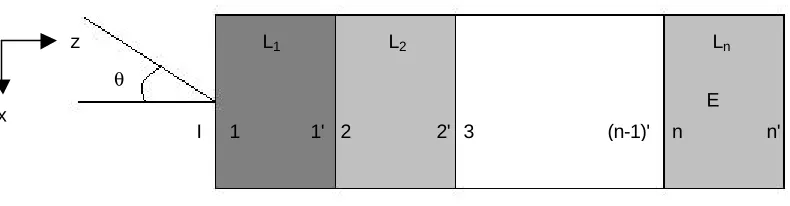
[image:2.596.102.497.152.255.2]1.1. Transfer matrix method
fig.1: multilayered structure
A multilayered structure as those represented by fig1. is considered. The transfer matrix method, used by various authors (Allard1, Brouard et al2) and well presented by Ghinet3, allows connecting incident boundary conditions VI to those of the end of the multilayer structure VE. Each layer Li is described by his own transfer matrix Ti that satisfies the relation :
Vi=Ti.Vi' (1)
Where Vi and Vi’ are vectors giving physical parameters (velocity, pressure, stress…) on the faces I and I’ of the considered layer.
The transfer matrix of a given layer depends on the physical and acoustical properties of the layer and of his thickness. At each interface, the continuities equations between the vector Vi' and Vi+1 can be represented in a matricial form with two matrices according to the relation:
Ii-1.V(i-1)'=Ii.Vi (2)
Then, the whole structure is represented by a global transfer matrix T which form is:
[ ]
[ ]
[ ]
[ ]
[ ]
[ ]
[ ]
[ ]
[ ] [ ] [ ]
[ ]
[ ] [ ] [ ]
[ ]
0 1 11 2 2
2 1 1
1
. 0 ... 0 0 0
0 . ... 0 0 0
... ... ... ... ... ... ...
0 0 0 ... . 0
0 0 0 ... 0 .
n n n
n n n
I I T
I I T
T
I I T
I I T
− − − − = (3)
In order to obtain the absorption coefficient or the transmission loss, two specific sets of boundary conditions are selected. For the absorption, the multilayer is considered backed by a rigid wall. For the transmission loss, the propagation is a semi-infinite domain of fluid (air). If matrices for elastic solids and homogeneous porous media exist, a special one should be developed for the transverse isotropic media
1.2. Dynamic characteristics for transverse isotropic media
First of all the porous media will be considered in this study with a motionless skeleton. By this way, only the compression wave in the fluid phase of the material is considered. The acoustical wave propagation is defined by the relation
0
eq eqp
j
p
K
ω
η
Π
− ∇ ⋅
∇ =
r
r
(4)Then, the porous media, from the macroscopic point of view is characterized by the dynamic compressibility
K
eqof the fluid phase and the dynamic permeability tensor
Π
eq
. This tensorwhich form is
1
0 0
0 0
0 0
eq x
eq eq y
eq z j ρ η ρ ω ρ − − − −
Π = (5)
x
z
I 1 1' 2 2' 3 (n-1)' n n'
E L2
L1 Ln
the dynamic density of the equivalent media is given by:
1 / 2 2
0 0
2 2 2 0
4
1 1
i i i
eq i
i i i
j j α ρ σφ α ηρ ρ ω φ ωρα σ φ ∞ ∞ − ∞ = − + Λ
(6)
The dynamic density depends on the properties of the saturating fluid: the kinematic viscosity
η
and the density ρ0; and on macroscopic intrinsic geometrical parameters: the open porosityφ
, and the vectorial values of the static airflow resistivityσ
i, the tortuosityα
∞i, and the viscous characteristic lengths Λi.When the motion of the rigid frame cannot be neglected, a more complex model describing poro-elastic media like the Biot-Allard’s1 one should be used. However for limp materials (when the solid frame has no bulk stiffness), Equation (4) still hold using the equivalent density given by:
(
)
2 0 2 2 0.
p eq l eq eq pρ ρ
ρ
ρ
ρ
ρ
ρ
−
=
+
−
(7)Where
ρ
p is the apparent density of the porous media.The dynamic compressibility has been detailed by Champoux5 . For materials like glass wools, the refined model of Lafarge et al's6 gives improved results and is used to calculate the dynamic compressibility.
1.3. Dynamic characteristics for transverse isotropic media
For a fluid, the transfer matrix is given by:
( )
( )
( )
( )
3 3 3 3 3 3 cos sin sin cos eqZ f eqZk e j k e
k T
k
j k e k e
ωρ ωρ = (8)
Considering Allard's1 relation for transverse isotropy, and including the dynamic parameters presented before, the impedance and the wave number in the case of oblique incidence are given by: 2 2 0 3 2 sin 1 Z X k k k k θ
= − , i eqi
eq
k
K
ρ
ω
=
andi
=
z x
,
(9)2. NUMERICAL RESULTS
2.1. Parameters of the porous media
The acoustic parameters of the porous medium chosen for the numerical calculus, have been measured on a standard glass wool of medium density (25 kgm-3)8. The ratio between the planar and the normal static air-flow resistivity is relatively low (0.74) compared to the ratio of 0.5 observed for glass wools by Allard et al7.
σ
(Nm-4s)φ
α
∞Λ
(µm)Λ
'
(µm) k0'(µm)z-direction 18600 1.08 46
x-direction 13800 1.00 54
x-direction, 0.5 ratio 9300
0.995
1.00 65
96 0.0029
2.2. Sound absorption coefficient
To estimate transverse isotropy incidence upon sound absorption of the material at oblique incidence, Allard's1 model is used to obtain the impedance of the material. The media considered has a thickness of e, and the oblique incidence has an angle θ with the normal of the material's surface. The impedance is given by the following relation:
3 3
.
Zcot
(
)
eqZ eq
k
Z
j
K
an k e
k
ρ
[image:4.596.188.403.167.311.2]= −
(10)fig. 2: Configuration to calculate sound absorption coefficient
On figure 3, absorption coefficient presents different values, for the limp model, between the isotropic and the transverse isotropic case only at a high angle of incidence as noticed by Allard1 in the case of rigid frame.
0 1 0 0 0 2 0 0 0 3 0 0 0 4 0 0 0 5 0 0 0 0
0.2 0.4 0.6 0.8 1
f r e q u e n c y H z
[image:4.596.181.414.373.511.2]absorption coefficient
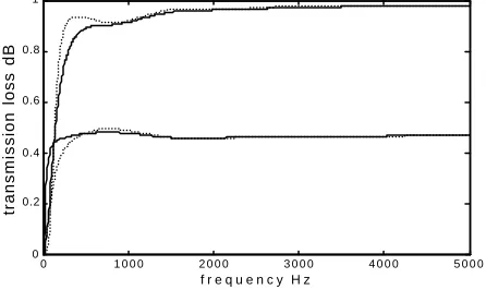
figure. 3: absorption coefficient for incidence of 30° and 85°, limp model. (continue line): isotropic case, (dot line) transverse isotropic case.
Influence of the limp model in the case of transverse isotropy , presented in figure 4, appears at low frequencies for low incidence angle, giving a higher absorption coefficient than the rigid model. The effect changes for high incidence angle, absorption becoming less under 800 Hz than values of the rigid model.
0 1 0 0 0 2 0 0 0 3 0 0 0 4 0 0 0 5 0 0 0 0
0.2 0.4 0.6 0.8 1
f r e q u e n c y H z
transmission loss dB
figure. 4: absorption coefficient for incidence of 30° and 85°, resistivity of 13800 Nm-4s.
(continue line): rigid model, (dot line) limp model. e
θ
z
x
[image:4.596.184.407.603.736.2]2.3. Transmission loss factor
[image:5.596.145.451.184.233.2]Transmission loss factor is calculated using the transfer matrix method as detailed before. The studied configuration is presented in fig 5. a lightweight wall composed of two gypsum plates separated by a layer of glass wool. The porous material in the cavity is separated from the plate by a thin air layer (1mm). The transmission loss is determined for incidence angles of 30 and 85 degrees.
fig. 5: structure of the multilayered system
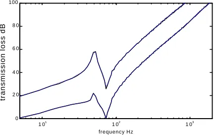
On figures 6 and 7 appear results of transmission loss for the rigid and limp model for the both cases of isotropy and transverse isotropy. For the two cases (limp and rigid), transverse isotropy cause no alteration of the transmission loss factor.
1 01
1 02
1 03
0 1 0 2 0 3 0 4 0 5 0 6 0 7 0 8 0 9 0 100
f r e q u e n c y H z
[image:5.596.184.405.299.434.2]transmission loss dB
Fig. 6 : transmission loss for incidence of 30° and 85°, rigid model. (continue line): isotropic case, (dot line) transverse isotropic case.
1 01
1 02
1 03
0 2 0 4 0 6 0 8 0 100
frequency Hz
[image:5.596.184.402.490.626.2]transmission loss dB
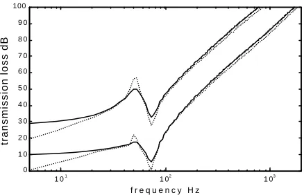
Fig. 7 : transmission loss for incidence of 30° and 85°, limp model. (continue line): isotropic case, (dot line) transverse isotropic case.
Figure 8 compares the effects of the rigid and the limp model on transmission loss factor. Generally, in the limp case, transmission loss becomes reduced essentially under the resonance frequency of the mass spring mass system. At high frequencies, the lost on the transmission loss isn’t as important that the one in low frequency range.
Gypsum plate 12.5mm Mineral wool
(100mm) Gypsum plate
1 01
1 02
1 03
0 1 0 2 0 3 0 4 0 5 0 6 0 7 0 8 0 9 0 100
f r e q u e n c y H z
[image:6.596.182.401.77.218.2]transmission loss dB
Fig. 8 : transmission loss for incidence of 30° and 85°,resistivity of 13800 Nm-4s.
(continue line): rigid model, (dot line) limp model.
3. CONCLUSION
Calculation shows that transverse isotropy, of the fluid phase due to the geometrical structure of the porous media, characterizing some porous material used for noise control purposes, has an influence on acoustic absorption only for high incidence angle compared to the isotropic model. No effects over transmission loss are observed for the mass-spring-mass system studied here. However, the limp model present important reduction of the transmission loss under the resonance frequency of the system. Except for materials presenting very strong transverse isotropic properties, the isotropic modeling stays efficient. Measurement should confirm these results.
6. REFERENCES
(1) J.F. Allard (1983), Propagation of sound in porous media, London and New York, Elsevier Applied Science.
(2) B. Brouard and D.Lafarge (1995), A general method of modelling sound propagation in layered media, J. of Sound and Vibration, 111111183(1), 129-142.
(3) S. Ghinet (2001), Etude numérique et optimisation de la perte par transmission des parois insonorisant multicouches, Memoire de maîtrise, Université de Sherbrooke, Canada.
(5) Y. Champoux (1991), Etude expérimentale du comportement acoustique de matériaux poreux à structure rigide (Experimental investigation of the acoustical behavior of rigid-frame porous material), Carleton University, Canada.
(4) D.L. Johnson, J. Koplik and R. Dashen (1987), Theory of dynamic permeability and tortuosity in fluid-saturated porous media, J. Fluid Mech., 176, 379-402.
(6) D. Lafarge, P. Lemarinier, J.F. Allard and V. Tarnow (1997), Dynamic compressibility of air in porous structures at audible frequencies, J. Acoust. Soc. Am., 102(4), 1995-2006
(7) J.F. Allard, R. Bourdier and A. L'Esperance (1987), Anisotropy effect in glass wool on normal impedance in oblique incidence, J. of Sound and Vibration, 114(2), 233-238.