DYNAMIC EFFECT OF HIGH SPEED RAILWAY TRAFFIC LOADS ON
THE BALLAST TRACK SETTLEMENT
K. Nguyen∗, J. M. Goicolea and F. Galbadón
Group of Computational Mechanics
School of Civil Engineering, Technical University of Madrid Calle Profesor Aranguren s/n, 28040, Madrid
e-mail: [email protected], web: http://w3.mecanica.upm.es
Keywords: track settlement, track deterioration, residual settlement, cyclic loading, settlement
models, train-track interaction
Abstract. The traditional ballast track structures are still being used in high speed railways
The requirements for the infrastructure, in the case of traditional ballasted track, represent a
considerable amount, in the order of 60 keper km and year. It is of course a priority to optimize
these costs and achieve a reduction in maintenance costs due to track quality deterioration and permanent settlements in ballasted track, which increase with velocity, traffic loads, number of load cycles and other factors. An essential ingredient for this is to be able to predict accurately these permanent settlements and track quality.
The deterioration of the track can be produced in different components of the track, gener-ally these components may be categorized into two groups: the superstructure and the substruc-ture. The settlement of the substructure is the main cause that produces the deterioration. The substructure of ballast track usually consists the ballast layer, a possible intermediate layer of sub-ballast and sub-grade. The ballast layer supports the track structure (rail and sleepers) and has several important functions:
• It limits sleeper movement by resisting vertical, transverse and longitudinal forces from
the trains.
• It distributes the load from the sleepers to protect the sub-grade from high stresses,
thereby limiting permanent settlement of track.
• It provides necessary resilience to absorb shock from dynamic loading.
However, it has not been yet reached a general consensus about adequate requirements for the ballast material index characteristics, such as particle size, particle shape, abrasion resistance and composition. Instead, the choice of a ballast material is commonly influenced by economic considerations and availability, where an extended variety of materials is used, such as a crushed granite, limestone, slag, and gravel. Figure 1 shows the typical profile of relative contribution of the substructure’s components to the track settlement. The ballast layer contributes the most to track settlement, compared to subballast and sub-grade.
Several models exist for predicting the evolution of the permanent settlement of the track as a function of time or traffic loads. Most of these involve empirical expressions that depend on such factors as train speed, traffic loading, number of loading cycles [21, 13, 19, 12, 4]. Other authors such as Suiker [22], Karg [16], Malek [1] have worked with more detailed elastic-plastic material models to simulate the permanent settlement and deterioration from cyclic loads.
Figure 1: Substructure contributions to settlement (from [20]).
for a study of prediction of the track settlement incorporating a settlement law to evaluate the dynamic effect on the ballast track settlement. The results obtained including the track profile growth and the contact force will be discussed and some future works will be suggested.
2 TRACK SETTLEMENT LAWS
The railway track will settle as a result of permanent deformation in the substructure such as ballast, subballast and subgrade. The settlement of ballasted track occurs in two major phases:
• Phase I: is relatively fast, usually occurs in the process of consolidation of ballast. During
this phase, the ballast is compressed to achieve high density.
• Phase II: after the first phase, the increment of settlement is slower, and with a more or
less linear relationship between settlement and time (or number of loading cycles).
The second phase of settlement is caused by several basic mechanisms of substructure behavior:
1. There is a continuous volume reduction, i.e. densification caused by particle rearrange-ment produced by repeated train loading.
2. Subballast and/or subgrade penetration into ballast voids takes place.
3. There is volume reduction caused by particle breakdown from train loading or environ-mental factors, by abrasive wear.
4. Movement of ballast and subgrade particles away from under the sleepers causes the sleepers to sink into the ballast/subgrade.
5. Lateral and possibility also longitudinal, movement of sleepers causes the ballast beneath the sleepers to be "pushed away", and the sleepers will sink deeper into the ballast.
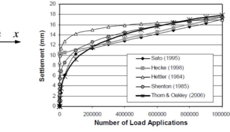
(a) Sato model [19] (b) Comparison of settlement prediction models from the literature ([24])
Figure 2: Settlement prediction models.
(or number of loading cycles), while the second phase tends to be linear. As the objective of this work is to predict the track settlement in function of the dynamic forces, we have examined some track settlement models which depend on the dynamic force such as Guérin model [12] that will be explained in more detail in the following subsection.
2.1 Guérin law (1996)
In an extensive study by Guérin [12], a laboratory test reduced to a scale(1-3) called “Mi-croballast” was used to investigate the ballast and subgrade settlement. Guérin’s work is based on the model proposed by Shenton [21]. Track settlement evolution is divided into two phases. In the first phase, mainly ballast compaction occurs, giving a ballast settlement rate that is rela-tively large. In the second phase the model includes a steady state settlement rate. In this phase,
the settlement rate (τ) per loading cycles (N) is expressed as a function of the maximum elastic
deflection (d) of the ballast and subgrade during the loading cycle:
dτ
dN =αd
β (1)
whereαandβare material parameters. For the material used in the experiment reported, Guérin
has determined the value of these parameters:α=0.48×10⁻⁶andβ=2.51 (with a coefficient of
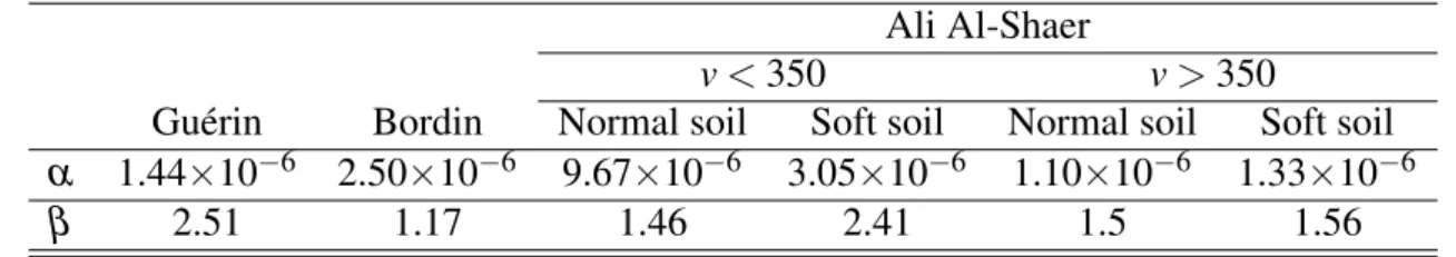
Table 1: Coefficientsα andβ for the Guérin, Bordin and Al-Shaer experiments.
Ali Al-Shaer
v<350 v>350
Guérin Bordin Normal soil Soft soil Normal soil Soft soil
α 1.44×10⁻⁶ 2.50×10⁻⁶ 9.67×10⁻⁶ 3.05×10⁻⁶ 1.10×10⁻⁶ 1.33×10⁻⁶
β 2.51 1.17 1.46 2.41 1.5 1.56
3 DYNAMIC ANALYSIS OF TRAIN-TRACK INTERACTION
3.1 Vehicle Models
Railway vehicles are complex mechanical multibody systems, including rigid body, linear and nonlinear springs and different types of damping that can be analyzed and designed using modern computational mechanics techniques. To simulate the dynamic vehicle-track interac-tion, several vehicle models have been used in research: from simple models such as a moving load to more complex models of multibody system in 3D. Often it is undesirable to employ sophisticated and complex vehicle models which are not well understood and whose details play no role in the vertical dynamic loads transmitted to the track infrastructure which is the objective here. The type of models to employ must be well understood and adequately selected. In this study, we developed different vehicle models in 2D and 3D, which takes into account the mass that vibrates with the deformation of the track.
3.1.1 2D vehicle model
For the 2D analysis, we have considered 5 models of train: from the simplest half axle model (or moving mass) to a more complex model of half vehicle (see figure 3). The vibrating masses considered are the masses of the wheel, bogie and train body. Depending on the model, primary and secondary suspensions consisting of discrete springs and dampers are also taken into account. In these models, the contact between wheel and rail is considered as a Hertz’s nonlinear spring. It was considered that the rail and wheel are the same material with the
elastic modulusE and Poisson’s ratioν, using Hertz’s normal elastic contact theory ([15]) the
nonlinear relationship between the vertical contact forceFvand the vertical relative deformation
δvis given by the relation (2).
Fv=δv3/2CH whereCH =
2E
3(1−ν2)(rrrw) 1/4
(2)
(a) 1/2 axle model (b) 1/4 bogie model (c) 1/8 vehicle model
(d) 1/2 bogie model (e) 1/2 vehicle model
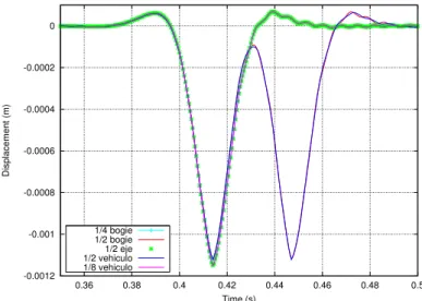
Figure 3: Two-dimensional vehicle models.
and has natural frequencies in the range of interest (f1= 220.9 Hz, f2 = 3.82 Hz) compared to
other excitation frequencies of the track. Therefore the 1/4 bogie model was used for this work.
-0.0012 -0.001 -0.0008 -0.0006 -0.0004 -0.0002 0
0.36 0.38 0.4 0.42 0.44 0.46 0.48 0.5
Displacement (m)
Time (s) 1/4 bogie
1/2 bogie 1/2 eje 1/2 vehiculo 1/8 vehiculo
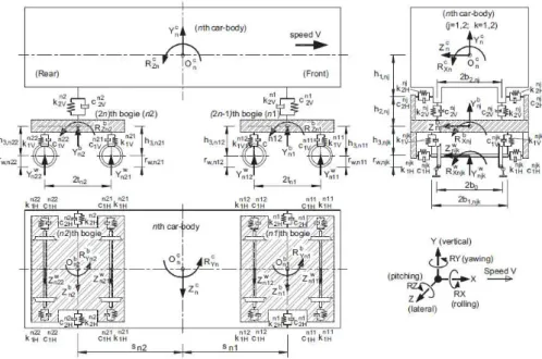
3.1.2 Full three-dimensional model of the vehicle
The vehicle is modeled using a multibody system with mechanical properties corresponding to the ICE 3 high speed vehicle (AVE S103) (figure 5). The considered vehicle model includes the box, bogies and wheelsets as rigid bodies with associated mass and inertia. Each rigid body has 6 degrees of freedom (DOF). The bodies are connected by two levels of suspension: primary and secondary. The suspension elements are modeled using springs and dampers with linear behavior. We have studied the modes of vibration of the vehicle modeled and the frequencies of the modes are obtained in the range of 0 to 40 Hz. Table 2 presents the first most representative modes of vibration of the vehicle.
Figure 5: Full three-dimensional vehicle (ICE3) models.
Vibration modes
No. of mode Frequency (Hz) Description
1 0.63973 Lateral movement and rolling car-body
2 0.75975 Vertical movement of car-body
3 0.94684 Pitching car-body
4 1.12670 Rolling bottom of car-body
5 3.28060 Yawing car-body and rolling bogies
(a) (b)
Figure 6: Model developed in Abaqus.
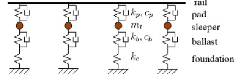
3.2 Track models
Generally, the structure of ballast track is composed by rail, railpads, sleepers, the ballast layer, the possible sub-ballast layer, the subgrade (see figure 7). The ballast track models in 2D and 3D have been developed.
Subgrade Sub-ballast Ballast
Rail Fastening Sleeper
(a) Longitudinal section
Ballast
Sub-ballast
Subgrade Sleeper
Rail
Fastening
(b) Transversal section
Figure 7: Structure of ballast track.
3.2.1 2D model
subsoil is modeled as an infinite linear elastic spring. The track length studied is 90.0 m (table 3)
Figure 8: Ballast track model in 2D
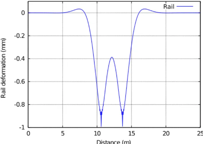
Figure 9 presents the vertical dynamic response of track in the frequency domain. Figure 10
1
2
3
Figure 9: Vertical dynamic response of track.
presents the static response of track when the force is applied at the centre of the track length studied, between two sleepers.
3.2.2 3D Model
mechan--1 -0.8
35 40 45 50 55
x(m)
Figure 10: Static response of ballast track 2D.
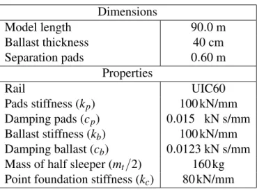
Dimensions
Model length 90.0 m
Ballast thickness 40 cm
Separation pads 0.60 m
Properties
Rail UIC60
Pads stiffness (kp) 100 kN/mm
Damping pads (cp) 0.015 kN s/mm
Ballast stiffness (kb) 100 kN/mm
Damping ballast (cb) 0.0123 kN s/mm
Mass of half sleeper (mt/2) 160 kg
Point foundation stiffness (kc) 80 kN/mm
Table 3: Model parameters of ballast track
ical properties of the materials are similar to the 2D model. To model the underlying soil is an important problem, as in principle a detailed 3D model should extend to infinity, in order to void reflection of shear and pressure waves transmitted from the structure. Of course practi-cal considerations make this unfeasible. In this study we have applied infinite elements which provide simultaneously the impedance of the foundations and non-reflecting boundaries, as im-plemented in Abaqus based on the work of Zienkiewicz [25] (see figure 11).
Rail
Railpads Sleeper
Ballast Sub-Ballast
Subground
Infinite Elements
Figure 11: Ballast track model in 3D developed in Abaqus.
-1 -0.8 -0.6 -0.4 -0.2 0
0 5 10 15 20 25
R
a
il
d
e
fo
rm
a
ti
o
n
(
m
m
)
Distance (m)
Rail
Figure 12: Vertical static response of ballast track 3D.
3.3 Vehicle-Track Interaction
In this part of the study, the train runs on the track with constant speed, taking into account the track irregularity profile (the wavelength is in range [3m-25m]). The irregularity is generated from the power spectral density (see [9]) according to maximum considered limit (intervention limit) defined in [8]. For dynamic analysis, we have applied three different generated irregular-ity profiles consistent with such limits (figure 13(a)). And the reverse process has been applied to verify the accuracy of the irregularities created (see figure 13(b)).
3.3.1 2D dynamic interaction
-0.004 -0.003
0 10 20 30 40 50 60 70 80 90
Vertical track irregularities (m)
Passing distance (m) D11 profile
D12 profile D13 profile
(a) Vertical irregularity profiles
1e-11 1e-10
0.01 0.1 1 10 100
Frequency [rad/m]
(b) Power spectral density
Figure 13: Generation of vertical irregularity profiles.
The calculation is done in the time domain, using the HHT time integration method to solve the transient problem. The contact problem is modeled by the method of Lagrange multipliers. The numerical simulations are done with different speeds (from 200 km/h to 360km/h) for each irregularity profile proposed and we have obtained the following results:
• Contact force between the wheel and the rail.
• Envelope of dynamic amplification of contact force in function of the speed.
0 20 40 60 80 100 120
0 0.1 0.2 0.3 0.4 0.5 0.6 0.7
Force [kN]
Time [s]
CaseIB360D11: Ballast Track 360 km/h, D1-1Profile
Contact Force Stactic Force
Maximum: 113.617 Dynamic Amplification:1.337
(a) D11 profile
0 20 40 60 80 100 120
0 0.1 0.2 0.3 0.4 0.5 0.6 0.7
Force [kN]
Time [s]
CaseIB360D12: Ballast Track 360 km/h, D1-2Profile
Contact Force Stactic Force
Maximum: 110.730 Dynamic Amplification:1.303
(b) D12 profile
1.1 1.15 1.2 1.25 1.3 1.35
200 220 240 260 280 300 320 340 360
Velocity [km/h]
F
a
ct
o
r of
d
yn
am
i
c
am
pl
if
ic
at
io
n D1-2 profileD1-1 profile
D1-3 profile Envelope
Figure 15: Envelope of dynamic amplification of contact force
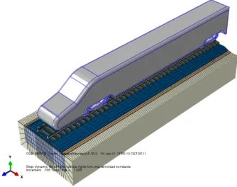
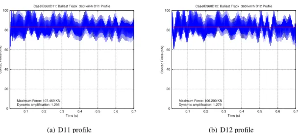
3.3.2 3D dynamic interaction
The analyses have been carried out using the 3D coupled vehicle/track model (figure 16). We obtained the contact force and the envelope of dynamic amplification of contact force in function of speed. The results obtained will be compared with the results in 2D dynamic interaction
3.3.1. Some representative results are shown in figure 17. We may observe that the results
Figure 16: Three-dimensional coupled vehicle/track model.
0 20
0.1 0.2 0.3 0.4 0.5 0.6 0.7 Time (s)
Maximum Force: 107.469 KN Dynamic amplification: 1.295
(a) D11 profile
0 20
0.1 0.2 0.3 0.4 0.5 0.6 0.7 Time (s)
Maximum Force: 106.200 KN Dynamic amplification: 1.279
(b) D12 profile
Figure 17: Contact force between wheel/rail at speed v=360km/h in 3D analysis.
200 220 240 260 280 300 320 340 360
1.1 1.15 1.2 1.25 1.3 1.35
Velocity (km/h)
Dynamic Amplification of Contact Force (KN)
Feap−D11 Feap−D12 Feap−D13 Abaqus−D11 Abaqus−D12 Abaqus−D13
Figure 18: Comparison of the results obtained in 3D analysis with 2D analysis.
4 PREDICTION OF TRACK SETTLEMENT
• Increment of number of loading cycle∆N = 50000 cycles.
• Maximum value of settlement: ymax= 5 mm.
• Maximum number of loading cycle:Nmax= 106cycles.
No
Yes
place. This is done for every interaction i, with ∆N cycles, until calculations reach a given
maximum settlement (in any point of track) or reach a given total number of loading cycles. The calculations were carried out in the dynamic model with different train running speeds (from 200 km/h to 360km/h).
Figure 20 presents the evolution of settlement with the increasing number of cycles for train speeds of 200 km/h and 360 km/h respectively. It may be noticed that for 360 km/h the set-tlement produced is greater. This result is consistent with what we obtained in the dynamic analysis in the previous section 3.3.1. In fact, when the train velocity increases the dynamic force increases too, producing correspondingly greater elastic deflection of ballast.
-4 -3 -2 -1 0 1 2
20 30 40 50 60 70 80 90 100
Vertical profile (mm)
Passing distance (m)
N =0.0e+00cycles N =5.0e+04cycles N =1.0e+05cycles N =1.5e+05cycles N =2.0e+05cycles N =2.5e+05cycles N =3.0e+05cycles N =3.5e+05cycles N =4.0e+05cycles N =4.5e+05cycles N =5.0e+05cycles N =5.5e+05cycles N =6.0e+05cycles N =6.5e+05cycles N =7.0e+05cycles N =7.5e+05cycles N =8.0e+05cycles N =8.5e+05cycles N =9.0e+05cycles N =9.5e+05cycles N =1.0e+06cycles
(a) Velocity of 200 km/h
-4 -3 -2 -1 0 1 2
20 30 40 50 60 70 80 90 100
Vertical profile (mm)
Passing distance (m)
N =0.0e+00cycles N =5.0e+04cycles N =1.0e+05cycles N =1.5e+05cycles N =2.0e+05cycles N =2.5e+05cycles N =3.0e+05cycles N =3.5e+05cycles N =4.0e+05cycles N =4.5e+05cycles N =5.0e+05cycles N =5.5e+05cycles N =6.0e+05cycles N =6.5e+05cycles N =7.0e+05cycles N =7.5e+05cycles N =8.0e+05cycles N =8.5e+05cycles N =9.0e+05cycles N =9.5e+05cycles N =1.0e+06cycles
(b) Velocity of 360 km/h
Figure 20: Track profile evolution with Guérin law
Figure 21 shows the settlement evolution in a point of track. It may be noticed that there is a
non-linear relationship between the settlement and the defectiond, and the settlement evolution
depends on the dynamic effect produced.
0 1 2 3 4 5 6 7 8 9 10 x 105 −1.6 −1.4 −1.2 −1 −0.8 −0.6 −0.4 −0.2 0 0.2 0.4
Number of loading cycles
Vertical Setllement (mm)
Velocity of 200 km/h Velocity of 360 km/h
Figure 21: Settlement evolution with different velocity
70 75 80 85 90
0 0.2 0.4 0.6 0.8 1 1.2 1.4
Contact Force (KN)
Time (s)
Case IB200D11: Ballast Track 200 km/h, D11 Profile
Contact force Static force
(a) Velocity of 200 km/h
20 40 60 80 100 120 140
0 0.2 0.4 0.6 0.8 1 1.2 1.4
Contact Force (KN)
Time (s)
Case IB360D11: Ballast Track 360 km/h, D11 Profile Contact force
Static force
(b) Velocity of 360 km/h
Figure 22: Contact Force
5 CONCLUSIONS
In this study, several vehicle/track finite element models have been analyzed and Guérin law has been incorporated in the numerical simulation to predict the evolution of track settlement. The results obtained indicate the influence on track irregularity evolution of the dynamic vehi-cle/track interaction. It is shown how the long-term behavior of ballast track may be predicted in detail from the dynamic loading of the track (number of loading cycles) an on the ballast de-flection due to that load. An increase of train speed will produce higher contact forces between the wheel and the rail, and will produce larger deflections in the ballast and a larger settlement will be obtained.
REFERENCES
[1] M. Abdelkrim, G. Bonnet, and P. de Buhan. A computational procedure for predicting the
long term residual settlement of a platform induced by repeated traffic loading.Computers
and Geotechnics, 30:463–476, 2003.
[2] A. Al-Shaer, D. Duhamel, K. Sab, G. Foret, and L.Schmitt. Experimental settlement and
dynamic behavior of a portion of ballasted railway track under high speed trains. Journal
of Sound and Vibration, 316:211–233, 2008.
[3] S. Augustin, G. gudehus, G. huber, and A. Schunemann. Numerical model and
labora-tory tests on settlement of ballast track. System Dynamics and Long-Term Behaviour of
Railway Vehicles, Track and Subgrade, 6:317–336, 2003.
[4] V. Bordin. Comportement du ballast des voices fereés soumises a un chargement vertical
et latéral. PhD thesis, Ecole Nationale des Ponts et Chaussées, Paris, 2001.
[5] Z. Cai and G. Raymond. Modelling the dynamic response of railway track to wheel/rail
impact loading. Structural Engineering and Mechanics, 2:95–112, 1994.
[6] CEN. EN 1991-2:2003, Eurocode 1: Actions on structures - Part 2: Traffic loads on
bridges. European Committee for Standardization, European Union, rue de Stassart,
36B-1050 Brussels, September 2003.
[7] CEN. EN 1990:2002/A1:2005 - Eurocode - Basis of Structural Design. Annex A2.
Ap-plication for Bridges. European Committee for Standardization, European Union, rue de
Stassart, 36B-1050 Brussels, December 2005.
[8] CEN. EN13848-5:2008 Railway Applications - Track - Track Geometry quality part 5:
Geometric quality levels. European Committee for Standardization - European Union, rue
de Stassart, 36B-1050 Brussels, march 2008.
[9] H. Clauss and W. Schiehlen. Modeling and simulation of railways bogie structural
vibra-tions. Vehicle System Dynamics, 29(S1):538–552, 1998.
[10] T. Dahlberg. Some railroad settlement models - a critical review. Proc. Institution of
[11] ERA. technical specification for interoperability relating to the infrastructure sub-system
of the trans-European high-speed rail system. European Railway Agency, European
Union, december 2007.
[12] N. Guérin. Approche expérimental et numérique du comportement du ballast des voices
ferrées. PhD thesis, Ecole Nationale des Pont et Chaussées, Paris, 1996.
[13] M. Ishida, A. Namura, and T. Suzuki. Track dynamic analysis for track settlement and
irregularity growth. Proc. Railway Engineering 2002, London, July 2002.
[14] M. Ishida and T. Suzuki. Effect on track settlement of interaction exited by leading and
trialing axles. QR of RTRI, 46(1), Feb (2005).
[15] K. Johnson. Contact Mechanics. Cambridge University Press, UK, 1985.
[16] C. Karg, S. François, W. Haegeman, and G. Degrande. Elasto-plastic long-term behavior
og granular soils: Modelling and experimental validation. Soil Dynamics and Earthquake
Engineering, 30:635–646, 2010.
[17] X. Lei and N. Noda. Analyses of dynamic response of vehicle and track coupling system
with random irregularity of track vertical profile. J. Sound Vib., 258:147–165, (2002).
[18] M. Pastor, O. C. Zienkiewicz, and H. C. Chan. Generalized plasticity and the modelling
of soil behavior. International Journal for Numerical and Analytical Methods in
Geome-chanics, 14:151–190, 1990.
[19] Y. Sato. Japanese studies on deterioration of ballasted track. Vehicle System Dynamics,
24(S1):197–208, 1995.
[20] E. Selig and J. Waters. Track Geotechnology and Substructure Management. Thomas
Telford Services Ltd, London, 1994.
[21] M. J. Shenton. Ballast deformation and trrack deterioration. In proceedings of a
Confer-ence on Track Technology, University of Nottingham:253–265, 11-13 July 1984.
[22] A. Suiker and R. de Borst. A numerical model for the ciclic deterioration of railway tracks.
International journal for numerical methods in engineering, 57:441–470, 2003.
[23] Y. Sun and M. Dhanasekar. A dyanmic model for the interaction of the rail track and
wagon system. International Journal of Solids and Structures, 39:1337–1359, 2002.
[24] N. Thom. Factors affecting trackbed maintenance requirements:a theoretical study.
Pro-ceedings of a Conference on Railway Engineering 07, London, 2007.
[25] O. Zienkiewicz, C. Emson, and P. Bettess. A novel boundary infinite element. Int. J.
![Figure 1: Substructure contributions to settlement (from [20]).](https://thumb-us.123doks.com/thumbv2/123dok_es/6798170.832970/3.892.277.608.198.366/figure-substructure-contributions-to-settlement-from.webp)