DIPLOMADO DE PROFUNDIZACION CISCO CCNP
EVALUACION – PRUEBA DE HABILIDADES PRACTICAS CCNP
LEONARDO FABIO AMAYA CACERES
UNIVERSIDAD NACIONAL ABIERTA Y A DISTANCIA - UNAD ESCUELA DE CIENCIAS BÁSICAS, TECNOLOGÍA E INGENIERÍA
INGENIERIA DE TELECOMUNICACIONES BOGOTA
DIPLOMADO DE PROFUNDIZACION CISCO CCNP
EVALUACION – PRUEBA DE HABILIDADES PRACTICAS CCNP
Autor
LEONARDO FABIO AMAYA CACERES Cod.1023927035
Director
GERARDO GRANADOS ACUÑA
UNIVERSIDAD NACIONAL ABIERTA Y A DISTANCIA - UNAD ESCUELA DE CIENCIAS BÁSICAS, TECNOLOGÍA E INGENIERÍA
INGENIERIA DE TELECOMUNICACIONES CEAD JOSE ACEVEDO Y GOMEZ
3
Nota de aceptación
Firma del presidente del jurado
Firma del jurado
Firma del jurado
4
DEDICATORIA
Primeramente, Quiero expresarle toda mi gratitud a Dios quien ha permitido que todo en cuanto hago en la vida me sea posible, también quiero agradecer a toda mi familia por siempre estar presentes en mi vida y apoyarme cuando estuve a punto de desfallecer.
Especialmente quiero agradecerle a mi hermana Carolina Amaya por brindarme su apoyo en los difíciles momentos y brindarme la motivación necesaria para continuar desarrollando mi carrera cada día.
5
CONTENIDO
Introduccion ... 8
Objetivo Principal ... 9
Desarrollo de los tres escenarios ... 10
Escenario 1 ... 10
Escenario 2 ... 28
Escenario 3 ... 39
Conclusiones ... 53
6
LISTA DE FIGURAS
Figura 1. Escenario 1 ... 10
Figura 2. Tabla de enrutamiento R3 ... 22
Figura 3. Rutas de sistema autónomo R1 ... 26
Figura 4. Rutas de sistema autónomo R1 ... 27
Figura 5. Escenario 2 ... 28
Figura 6. Relación de vecino BGP entre R1 y R2 ... 34
Figura 7. Relación de vecino BGP entre R1 y R2 ... 35
Figura 8. Relación de vecino BGP entre R2 y R3 ... 36
Figura 9. Relación de vecino BGP entre R2 y R3 ... 37
Figura 10. Red Loopback de R4 en BGP. ... 38
Figura 11. Escenario 3 ... 39
Figura 12. VTP Estatus escenario 3 SWT1 ... 41
Figura 13. VTP Estatus escenario 3 SWT2 ... 41
Figura 14. VTP Estatus escenario 3 SWT3 ... 42
Figura 15. Enlace TRUNK SWT1 ... 43
Figura 16. Enlace TRUNK SWT2 ... 43
Figura 17. Enlace TRUNK estático SWT1 ... 44
7
LISTA DE TABLAS
Tabla 1. Interface Loopback R1 Escenario1 ... 18
Tabla 2. Interface Loopback R5 Escenario 1. ... 21
Tabla 3. Interfaz Routers Escenario 2. ... 28
Tabla 4. Interfaces / VLAN Escenario 3. ... 47
8
Introduccion
Dentro de la ingenieria de telecomunicaciones es fundamental el conocer el funcionamiento y configuracion de los perifericos mas importantes y fundamentales como lo son los Siwtch y Router, es por ello que dentro del presente archivo documentaremos las practicas realizadas, en busca de aplicar todo el conocimiento adquirido dentro del diplomado Cisco CCNP. Dicho diplomado nos permitio establecer las bases de configuracion de los diferentes dispositivos de comunicaciones y logramos identificar lo fundamental de aplicar una buena configuracion teniendo en cuenta que, se nos presenta un si numero de oportunidades de mejora, en la infraestructura, seguridad y calidad de nuestra red de datos.
9
Objetivo Principal
Aplicar los conocimientos recogidos durante la realizacion del diplomado de profundizacion Cisco CCNP por medio de la aplicación de habilidades practicas.
Objetivos Especificos
➢ Aplicar las configuraciones minimas a un Router y Swith dentro de nuestras practicas y redes de datos
➢ Establecer reglas de conectividad dentro de los perifericos con el fin de permitir o no el flujo de datos
➢ Conocer la informacion basica aplicada a los protocolos OSFP aplicado a nuestros Router.
10
Desarrollo de los tres escenarios Escenario 1
No se encuentran elementos de tabla de ilustraciones.
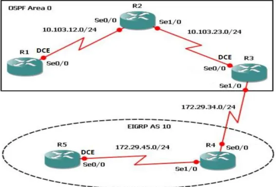
Figura 1. Escenario 1
1. Aplique las configuraciones iniciales y los protocolos de enrutamiento para los routers R1, R2, R3, R4 y R5 según el diagrama. No asigne passwords en los routers. Configurar las interfaces con las direcciones que se muestran en la topología de red.
Aplicamos la configuración del R1 R1(config)#no ip domai
R1(config)#no ip domain-lookup R1(config)#line con 0
R1(config-line)#log R1(config-line)#logg
R1(config-line)#logging sync
11 R1(config-line)#exce
R1(config-line)#exec
R1(config-line)#exec-timeout 0 0 R1(config-line)#
R1(config-line)#exi R1(config)#inter
R1(config)#interface lo
R1(config)#interface loopback 1
R1(config-if)#
%LINK-5-CHANGED: Interface Loopback1, changed state to up
%LINEPROTO-5-UPDOWN: Line protocol on Interface Loopback1, changed state to up R1(config-if)#inter R1(config-if)#interfas R1(config-if)#inter R1(config-if)#interfa R1(config-if)#interface R1(config-if)#interface ser
R1(config-if)#interface serial 0/0/0
R1(config-if)#ip address 10.103.12.2 255.255.255.0 R1(config-if)#
R1(config-if)#clock rate 128000 R1(config-if)#no shu
%LINK-5-CHANGED: Interface Serial0/0/0, changed state to down R1(config-if)#exi
R1(config)#exi R1#
%SYS-5-CONFIG_I: Configured from console by console
R1#config ter R1#config terminal
Enter configuration commands, one per line. End with CNTL/Z. R1(config)#router
R1(config)#router os R1(config)#router ospf 1 R1(config-router)#router
R1(config-router)#router-id 1.1.1.1 R1(config-router)#netq
R1(config-router)#netw
12 R1(config-router)#exi
R1(config)#exi R1#
%SYS-5-CONFIG_I: Configured from console by console R1#copy ru st
Destination filename [startup-config]? Building configuration...
[OK] R1#
Aplicamos la configuración del R2 Router>enable
Router#conf
Configuring from terminal, memory, or network [terminal]? ter Enter configuration commands, one per line. End with CNTL/Z. Router(config)#no ip domain-lookup
Router(config)#line con 0 Router(config-line)#
Router(config-line)#logging synchronous Router(config-line)#exec-timeout 0 0 Router(config-line)#exit
Router(config)#interface loopback 2
Router(config-if)#
%LINK-5-CHANGED: Interface Loopback2, changed state to up
%LINEPROTO-5-UPDOWN: Line protocol on Interface Loopback2, changed state to up
Router(config-if)#interface serial 0/0/0
Router(config-if)#ip address 10.103.12.1 255.255.255.0 Router(config-if)#no shu
Router(config-if)#
%LINK-5-CHANGED: Interface Serial0/0/0, changed state to up
Router(config-if)#
%LINEPROTO-5-UPDOWN: Line protocol on Interface Serial0/0/0, changed state to up
Router(config-if)#interface serial 0/0/1 Router(config-if)#interface serial 0/0/1 Router(config-if)#
13 Router(config-if)#
Router(config-if)#no shu
%LINK-5-CHANGED: Interface Serial0/0/1, changed state to down Router(config-if)#exi
Router(config)#router
Router(config)#rorrouter ospf 1
Router(config-router)#router-id 2.2.2.2
Router(config-router)#network 10.103.12.0 0.0.0.255 area 0 Router(config-router)#
00:12:19: %OSPF-5-ADJCHG: Process 1, Nbr 1.1.1.1 on Serial0/0/0 from LOADING to FULL, Loading Done
Router(config-router)#network 10.103.23.0 0.0.0.255 area 0 Router(config-router)#
Router(config-router)#exi Router(config)#exi
Router#
%SYS-5-CONFIG_I: Configured from console by console
Router#soscopy ru st
Destination filename [startup-config]? Building configuration...
[OK] Router#
Router#configure terminal
Enter configuration commands, one per line. End with CNTL/Z. Router(config)#hostname R2
R2(config)# R2(config)#
%LINK-5-CHANGED: Interface Serial0/0/1, changed state to up
Aplicamos la configuración del R3
Router>enable
Router#configure terminal
Enter configuration commands, one per line. End with CNTL/Z. Router(config)#hostname R3
R3(config)#no ip domain-lookup R3(config)#line con 0
14 R3(config-line)#exi
R3(config)#interface loopback 3
R3(config-if)#
%LINK-5-CHANGED: Interface Loopback3, changed state to up
%LINEPROTO-5-UPDOWN: Line protocol on Interface Loopback3, changed state to up
R3(config-if)#interface serial 0/0/1
R3(config-if)#ip address 10.103.23.1 255.255.255.0 R3(config-if)#clock rate 128000
This command applies only to DCE interfaces R3(config-if)#exi
R3(config)#inter
R3(config)#interface lop R3(config)#interface loop
R3(config)#interface loopback 3 R3(config-if)#inter
R3(config-if)#interfa R3(config-if)#interface
R3(config-if)#interface serial 0/0/1
R3(config-if)#ip address 10.103.23.1 255.255.255.0 R3(config-if)#clock rate 128000
This command applies only to DCE interfaces R3(config-if)#no shu
R3(config-if)#
%LINK-5-CHANGED: Interface Serial0/0/1, changed state to up
R3(config-if)#exi R3(config)#int
% Incomplete command. R3(config)#
%LINEPROTO-5-UPDOWN: Line protocol on Interface Serial0/0/1, changed state to up
R3(config)#interface loopback 3 R3(config-if)#interface serial 0/0/0
R3(config-if)#ip address 172.29.34.2 255.255.255.0 R3(config-if)#no shutdown
%LINK-5-CHANGED: Interface Serial0/0/0, changed state to down R3(config-if)#exi
15 R3#
%SYS-5-CONFIG_I: Configured from console by console
R3#en R3#config
Configuring from terminal, memory, or network [terminal]? ter Enter configuration commands, one per line. End with CNTL/Z. R3(config)#router ospf 1
R3(config-router)#router-id 3.3.3.3
R3(config-router)#network 10.103.23.0 0.0.0.255 area 0 R3(config-router)#exio
^
% Invalid input detected at '^' marker. R3(config-router)#exi
R3(config)#exi R3#
%SYS-5-CONFIG_I: Configured from console by console
R3#copy R3#copy run
R3#copy running-config
00:35:43: %OSPF-5-ADJCHG: Process 1, Nbr 2.2.2.2 on Serial0/0/1 from LOADING to FULL, Loading Done
R3#copy running-config sta
R3#copy running-config startup-config Destination filename [startup-config]? Building configuration...
[OK] R3#
%LINK-5-CHANGED: Interface Serial0/0/0, changed state to up
%LINEPROTO-5-UPDOWN: Line protocol on Interface Serial0/0/0, changed state to up
Aplicamos la configuración del R4
Router>enable
Router#configure terminal
Enter configuration commands, one per line. End with CNTL/Z. Router(config)#hostname R4
16 R4(config)#no ip domain-lookup
R4(config)#line con 0
R4(config-line)#logging synchronous R4(config-line)#exec-timeout 0 0 R4(config-line)#exit
R4(config)#interface loopback 4
R4(config-if)#
%LINK-5-CHANGED: Interface Loopback4, changed state to up
%LINEPROTO-5-UPDOWN: Line protocol on Interface Loopback4, changed state to up
R4(config-if)#interface serial 0/0/0 R4(config-if)#
R4(config-if)#ip address 172.29.34.1 255.255.255.0 R4(config-if)#
R4(config-if)#no shut
R4(config-if)#
%LINK-5-CHANGED: Interface Serial0/0/0, changed state to up
R4(config-if)#
%LINEPROTO-5-UPDOWN: Line protocol on Interface Serial0/0/0, changed state to up
R4(config-if)#interface serial 0/0/1
R4(config-if)#ip address 172.29.45.2 255.255.255.0 R4(config-if)#no shut
%LINK-5-CHANGED: Interface Serial0/0/1, changed state to down R4(config-if)#exi
R4(config)#exi R4#
%SYS-5-CONFIG_I: Configured from console by console
R4#copy run
R4#copy running-config s R4#copy running-config star
R4#copy running-config startup-config Destination filename [startup-config]? Building configuration...
[OK] R4#
17
%LINEPROTO-5-UPDOWN: Line protocol on Interface Serial0/0/1, changed state to up
Aplicamos la configuración del R5 Router>ena
Router#conf
Configuring from terminal, memory, or network [terminal]? ter Enter configuration commands, one per line. End with CNTL/Z. Router(config)#
Router(config)#no ip domain-lookup Router(config)#
Router(config)#line con Router(config)#line con 0
Router(config-line)#logging synchronous Router(config-line)#exec-timeout 0 0 Router(config-line)#
Router(config-line)#exit
Router(config)#interface loopback 5
Router(config-if)#
%LINK-5-CHANGED: Interface Loopback5, changed state to up
%LINEPROTO-5-UPDOWN: Line protocol on Interface Loopback5, changed state to up
Router(config-if)#interface serial 0/0/0 Router(config-if)#interface serial 0/0/1
Router(config-if)#ip address 172.29.45.1 255.255.255.0 Router(config-if)#clock rate 128000
This command applies only to DCE interfaces Router(config-if)#no shut
Router(config-if)#
%LINK-5-CHANGED: Interface Serial0/0/1, changed state to up
Router(config-if)#
%LINEPROTO-5-UPDOWN: Line protocol on Interface Serial0/0/1, changed state to up
e
18
%SYS-5-CONFIG_I: Configured from console by console
Router#copy run
Router#copy running-config st
Router#copy running-config startup-config Destination filename [startup-config]? Building configuration...
[OK] Router#
Router#configure terminal
Enter configuration commands, one per line. End with CNTL/Z. Router(config)#hostname R5
R5(config)#
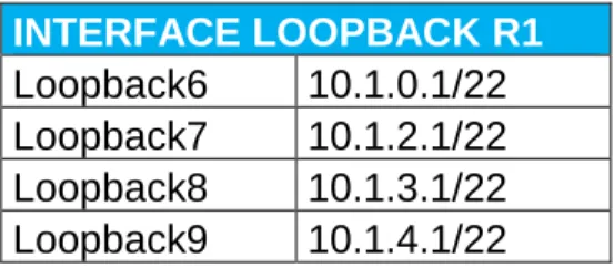
2. Cree cuatro nuevas interfaces de Loopback en R1 utilizando la asignación de direcciones 10.1.0.0/22 y configure esas interfaces para participar en el área 0 de OSPF.
Tabla 1. Interface Loopback R1 Escenario1
INTERFACE LOOPBACK R1 Loopback6 10.1.0.1/22 Loopback7 10.1.2.1/22 Loopback8 10.1.3.1/22 Loopback9 10.1.4.1/22 R1#
R1#ena R1#config
Configuring from terminal, memory, or network [terminal]? ter Enter configuration commands, one per line. End with CNTL/Z. R1(config)#inter
R1(config)#interface loop
R1(config)#interface loopback 6
R1(config-if)#
%LINK-5-CHANGED: Interface Loopback6, changed state to up
%LINEPROTO-5-UPDOWN: Line protocol on Interface Loopback6, changed state to up
R1(config-if)#ip add
19 R1(config)#inter
R1(config)#interface lop R1(config)#interface loop
R1(config)#interface loopback 7
R1(config-if)#
%LINK-5-CHANGED: Interface Loopback7, changed state to up
%LINEPROTO-5-UPDOWN: Line protocol on Interface Loopback7, changed state to up
R1(config-if)#ip ad
R1(config-if)#ip address 10.1.2.1 255.255.255.0 R1(config-if)#exi
R1(config)#inter
R1(config)#interface lop R1(config)#interface loop
R1(config)#interface loopback 8
R1(config-if)#
%LINK-5-CHANGED: Interface Loopback8, changed state to up
%LINEPROTO-5-UPDOWN: Line protocol on Interface Loopback8, changed state to up
R1(config-if)#ip ad
R1(config-if)#ip address 10.1.3.1 255.255.255.0 R1(config-if)#exi
R1(config)#inter
R1(config)#interface lop R1(config)#interface loop
R1(config)#interface loopback 9
R1(config-if)#
%LINK-5-CHANGED: Interface Loopback9, changed state to up
%LINEPROTO-5-UPDOWN: Line protocol on Interface Loopback9, changed state to up
R1(config-if)#ip ad
R1(config-if)#ip address 10.1.4.1 255.255.255.0 R1(config-if)#exi
20 R1(config)#router osp
R1(config)#router ospf 1 R1(config-router)#router
R1(config-router)#router-id 1.1.1.1 R1(config-router)#net
R1(config-router)#network 10.1.0.0 0.0.3.255 area 0 R1(config-router)#net
R1(config-router)#network 10.103.12.0 % Incomplete command.
R1(config-router)#exi R1(config)#rout R1(config)#router osp R1(config)#router ospf 1 R1(config-router)#net
R1(config-router)#network 10.103.12.0 0.0.0.255 area 0 R1(config-router)#exi
R1(config)#exi R1#
%SYS-5-CONFIG_I: Configured from console by console
R1#conf
Configuring from terminal, memory, or network [terminal]? ter Enter configuration commands, one per line. End with CNTL/Z. R1(config)#interface lo
R1(config)#interface loopback 6 R1(config-if)#ip ois
R1(config-if)#ip os R1(config-if)#ip ospf net
R1(config-if)#ip ospf network po
R1(config-if)#ip ospf network point-to-point R1(config-if)#exi
R1(config)#interface loopback 7
R1(config-if)#ip ospf network point-to-point R1(config-if)#exi
R1(config)#interface loopback 8
R1(config-if)#ip ospf network point-to-point R1(config-if)#exi
R1(config)#interface loopback 9
R1(config-if)#ip ospf network point-to-point R1(config-if)#exi
R1(config)#exi R1#
%SYS-5-CONFIG_I: Configured from console by console
21 R1#copy running-config sta
R1#copy running-config startup-config Destination filename [startup-config]? Building configuration...
[OK
3. Cree cuatro nuevas interfaces de Loopback en R5 utilizando la asignación de direcciones 172.5.0.0/22 y configure esas interfaces para participar en el Sistema Autónomo EIGRP 10.
Tabla 2. Interface Loopback R5 Escenario 1.
INTERFACE LOOPBACK R5 Loopback16 172.5.0.1/22 Loopback17 172.5.4.1/22 Loopback18 172.5.8.1/22 Loopback19 172.5.12.1/22
%LINEPROTO-5-UPDOWN: Line protocol on Interface Loopback19, changed state to up
R5(config-if)#exi
R5(config)#interface loopback 16
R5(config-if)#ip address 172.5.0.1 255.255.252.0 R5(config-if)#exi
R5(config)#interface loopback 17
R5(config-if)#ip address 172.5.4.1 255.255.252.0 R5(config-if)#exi
R5(config)#interface loopback 18
R5(config-if)#ip address 172.5.8.1 255.255.252.0 R5(config-if)#exi
R5(config)#interface loopback 19
R5(config-if)#ip address 172.5.12.1 255.255.252.0 R5(config-if)#exi
R5(config)#route R5(config)#route eig R5(config)#route eigrp 10 R5(config-router)#aut
R5(config-router)#auto-summary R5(config-router)#net
R5(config-router)#network 172.5.0.0 0.0.3.255 R5(config-router)#network 172.29.45.0 0.0.0.255 R5(config-router)#exi
22 R5#
%SYS-5-CONFIG_I: Configured from console by console
R5#copy run
R5#copy running-config sta
R5#copy running-config startup-config Destination filename [startup-config]? Building configuration...
[OK]
4. Analice la tabla de enrutamiento de R3 y verifique que R3 está aprendiendo las nuevas interfaces de Loopback mediante el commando show ip route.
23
5. Configure R3 para redistribuir las rutas EIGRP en OSPF usando el costo de 50000 y luego redistribuya las rutas OSPF en EIGRP usando un ancho de banda T1 y 20,000 microsegundos de retardo.
R3(config)#routter R3(config)#router R3(config)#router os R3(config)#router ospf 10 R3(config-router)#redis
R3(config-router)#redistribute eig
R3(config-router)#redistribute eigrp 10 sub R3(config-router)#redistribute eigrp 10 subnets R3(config-router)#exi
R3(config)#router R3(config)#router osp R3(config)#router ospf 1 R3(config-router)#redis
R3(config-router)#redistribute ei
R3(config-router)#redistribute eigrp 10
% Only classful networks will be redistributed R3(config-router)#redis
R3(config-router)#redistribute eig
R3(config-router)#redistribute eigrp 10 sub R3(config-router)#redistribute eigrp 10 subnets R3(config-router)#exi
R3(config)#router R3(config)#router eig R3(config)#router eigrp 10 R3(config-router)#redis
R3(config-router)#redistribute os R3(config-router)#redistribute ospf 1 R3(config-router)#redistribute ospf 1 me
R3(config-router)#redistribute ospf 1 metric 154
R3(config-router)#redistribute ospf 1 metric 1544 100 255 1 % Incomplete command.
R3(config-router)#redistribute ospf 1 metric 1544 100 255 1 % Incomplete command.
R3(config-router)#redistribute ospf 1 metric 1544 100 255 1 % Incomplete command.
R3(config-router)#redistribute ospf 1 metric 1544 100 255 1 1500 R3(config-router)#exi
R3(config)#exi R3#
24 R3#show{
R3#show ip R3#show ip r R3#show ip route
Codes: L - local, C - connected, S - static, R - RIP, M - mobile, B - BGP D - EIGRP, EX - EIGRP external, O - OSPF, IA - OSPF inter area N1 - OSPF NSSA external type 1, N2 - OSPF NSSA external type 2 E1 - OSPF external type 1, E2 - OSPF external type 2, E - EGP i - IS-IS, L1 - IS-IS level-1, L2 - IS-IS level-2, ia - IS-IS inter area * - candidate default, U - per-user static route, o - ODR
P - periodic downloaded static route
Gateway of last resort is not set
10.0.0.0/8 is variably subnetted, 6 subnets, 2 masks
O 10.1.0.0/24 [110/129] via 10.103.23.2, 00:21:25, Serial0/0/1 O 10.1.2.0/24 [110/129] via 10.103.23.2, 00:21:13, Serial0/0/1 O 10.1.3.0/24 [110/129] via 10.103.23.2, 00:20:55, Serial0/0/1 O 10.103.12.0/24 [110/128] via 10.103.23.2, 00:44:43, Serial0/0/1 C 10.103.23.0/24 is directly connected, Serial0/0/1
L 10.103.23.1/32 is directly connected, Serial0/0/1 172.29.0.0/16 is variably subnetted, 2 subnets, 2 masks C 172.29.34.0/24 is directly connected, Serial0/0/0 L 172.29.34.2/32 is directly connected, Serial0/0/0
R3#conf
Configuring from terminal, memory, or network [terminal]? ter Enter configuration commands, one per line. End with CNTL/Z. R3(config)#router
R3(config)#router os R3(config)#router ospf 1 R3(config-router)#net
R3(config-router)#network 172.29.34.0 0.0.0.255 are R3(config-router)#network 172.29.34.0 0.0.0.255 area 0 R3(config-router)#exi
R3(config)#exi R3#
%SYS-5-CONFIG_I: Configured from console by console
R3#show ip route
25
i - IS-IS, L1 - IS-IS level-1, L2 - IS-IS level-2, ia - IS-IS inter area * - candidate default, U - per-user static route, o - ODR
P - periodic downloaded static route
Gateway of last resort is not set
10.0.0.0/8 is variably subnetted, 6 subnets, 2 masks
O 10.1.0.0/24 [110/129] via 10.103.23.2, 00:22:04, Serial0/0/1 O 10.1.2.0/24 [110/129] via 10.103.23.2, 00:21:52, Serial0/0/1 O 10.1.3.0/24 [110/129] via 10.103.23.2, 00:21:34, Serial0/0/1 O 10.103.12.0/24 [110/128] via 10.103.23.2, 00:45:22, Serial0/0/1 C 10.103.23.0/24 is directly connected, Serial0/0/1
L 10.103.23.1/32 is directly connected, Serial0/0/1 172.29.0.0/16 is variably subnetted, 2 subnets, 2 masks C 172.29.34.0/24 is directly connected, Serial0/0/0 L 172.29.34.2/32 is directly connected, Serial0/0/0
R3#conf
Configuring from terminal, memory, or network [terminal]? ter Enter configuration commands, one per line. End with CNTL/Z. R3(config)#route
R3(config)#router os R3(config)#router ospf 1 R3(config-router)#redis
R3(config-router)#redistribute eig
R3(config-router)#redistribute eigrp 10 sub R3(config-router)#redistribute eigrp 10 subnets R3(config-router)#log
R3(config-router)#log-adjacency-changes R3(config-router)#redis
R3(config-router)#redistribute ei R3(config-router)#redistribute eigrp 7 R3(config-router)#redistribute eigrp 7 sub R3(config-router)#redistribute eigrp 7 subnets R3(config-router)#net
R3(config-router)#network 172.29.45.0 0.0.0.255 area 0 R3(config-router)#exi
R3(config)#router R3(config)#router eig R3(config)#router eigrp 10 R3(config-router)#redis
R3(config-router)#redistribute osfp 1 me
R3(config-router)#redistribute osfp 1 metric 50000 200 255 1 1500 ^
26 R3(config-router)#redistribu
R3(config-router)#redistribute os R3(config-router)#redistribute ospf 1 R3(config-router)#redistribute ospf 1 me
R3(config-router)#redistribute ospf 1 metric 50000 200 255 1 1500 R3(config-router)#aud
R3(config-router)#auto
R3(config-router)#auto-summary R3(config-router)#exit
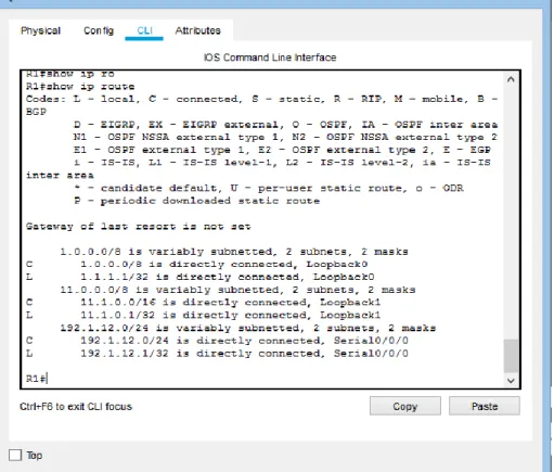
6. Verifique en R1 y R5 que las rutas del sistema autónomo opuesto existen en su tabla de enrutamiento mediante el comando show ip route.
27
28 Escenario 2
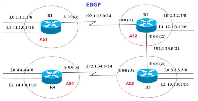
Figura 5. Escenario 2
Tabla 3. Interfaz Routers Escenario 2.
Interfaz R1 Dirección IP Máscara
Loopback 0 1.1.1.1 255.0.0.0
Loopback 1 11.1.0.1 255.255.0.0
S 0/0 192.1.12.1 255.255.255.0
Interfaz R2 Dirección IP Máscara
Loopback 0 2.2.2.2 255.0.0.0
Loopback 1 12.1.0.1 255.255.0.0
S 0/0 192.1.12.2 255.255.255.0
E 0/0 192.1.23.2 255.255.255.0
Interfaz R3 Dirección IP Máscara
Loopback 0 3.3.3.3 255.0.0.0
Loopback 1 13.1.0.1 255.255.0.0
E 0/0 192.1.23.3 255.255.255.0
29
Interfaz R4 Dirección IP Máscara
Loopback 0 4.4.4.4 255.0.0.0
Loopback 1 14.1.0.1 255.255.0.0
S 0/0 192.1.34.4 255.255.255.0
Configuración inicial router 1 Router>enable
Router#configure terminal
Enter configuration commands, one per line. End with CNTL/Z. Router(config)#hostname R1
R1(config)# R1(config)# R1(config)# R1(config)#inter
R1(config)#interface lo
R1(config)#interface loopback 0
R1(config-if)#
%LINK-5-CHANGED: Interface Loopback0, changed state to up
%LINEPROTO-5-UPDOWN: Line protocol on Interface Loopback0, changed state to up
R1(config-if)#ip ad
R1(config-if)#ip address 1.1.1.1 255.0.0.0 R1(config-if)#exit
R1(config)#inter
R1(config)#interface lop R1(config)#interface loo
R1(config)#interface loopback 1
R1(config-if)#
%LINK-5-CHANGED: Interface Loopback1, changed state to up
%LINEPROTO-5-UPDOWN: Line protocol on Interface Loopback1, changed state to up
R1(config-if)#ip ad
30 R1(config-if)#exi
R1(config)#inter
R1(config)#interface se
R1(config)#interface serial 0/0/0 R1(config-if)#ip ad
R1(config-if)#ip address 192.1.12.1 255.255.255.0 R1(config-if)#clo
R1(config-if)#clockra R1(config-if)#clock ra
R1(config-if)#clock rate 64000 R1(config-if)#no shu
%LINK-5-CHANGED: Interface Serial0/0/0, changed state to down R1(config-if)#exit
Configuración inicial router 2 Router#configure terminal
Enter configuration commands, one per line. End with CNTL/Z. Router(config)#hostname R2
R2(config)# R2(config)#enab R2(config)#enable
% Incomplete command. R2(config)#int
R2(config)#interface lo
R2(config)#interface loopback 0
R2(config-if)#
%LINK-5-CHANGED: Interface Loopback0, changed state to up
%LINEPROTO-5-UPDOWN: Line protocol on Interface Loopback0, changed state to up
R2(config-if)#ip ad
R2(config-if)#ip address 2.2.2.2 255.0.0.0 R2(config-if)#exit
R2(config)#inter
R2(config)#interface lop R2(config)#interface loo
R2(config)#interface loopback 1
R2(config-if)#
31
%LINEPROTO-5-UPDOWN: Line protocol on Interface Loopback1, changed state to up
R2(config-if)#ip ad
R2(config-if)#ip address 12.1.0.1 255.255.0.0 R2(config-if)#exi
R2(config)#inter
R2(config)#interface ser
R2(config)#interface serial 0/0/0 R2(config-if)#ip ad
R2(config-if)#ip address 192.1.12.2 255.255.255.0 R2(config-if)#no shu
R2(config-if)#
%LINK-5-CHANGED: Interface Serial0/0/0, changed state to up exi
R2(config)#inter
R2(config)#interface gi
R2(config)#interface gigabitEthernet 0/0
%LINEPROTO-5-UPDOWN: Line protocol on Interface Serial0/0/0, changed state to up
R2(config-if)#ip ad
R2(config-if)#ip address 192.1.23.2 255.255.255.0
Configuración inicial router 3
Enter configuration commands, one per line. End with CNTL/Z. Router(config)#hostname R3
R3(config)#inter
R3(config)#interface loi R3(config)#interface loop
R3(config)#interface loopback 0
R3(config-if)#
%LINK-5-CHANGED: Interface Loopback0, changed state to up
%LINEPROTO-5-UPDOWN: Line protocol on Interface Loopback0, changed state to up
R3(config-if)#ip ad
R3(config-if)#ip address 3.3.3.3 255.0.0.0 R3(config-if)#exi
R3(config)#inter
32 R3(config)#interface loopback 1
R3(config-if)#
%LINK-5-CHANGED: Interface Loopback1, changed state to up
%LINEPROTO-5-UPDOWN: Line protocol on Interface Loopback1, changed state to up
R3(config-if)#ip ad
R3(config-if)#ip address 13.1.0.1 255.255.0.0 R3(config-if)#exit
R3(config)#inter
R3(config)#interface gi
R3(config)#interface gigabitEthernet 0/0 R3(config-if)#192.1.23.3 255.255.255.0 ^
% Invalid input detected at '^' marker.
R3(config-if)#ip addres 192.1.23.3 255.255.255.0 R3(config-if)#no shu
R3(config-if)#
%LINK-5-CHANGED: Interface GigabitEthernet0/0, changed state to up
%LINEPROTO-5-UPDOWN: Line protocol on Interface GigabitEthernet0/0, changed state to up
R3(config-if)#inter R3(config-if)#exi R3(config)#inter R3(config)#interface s
R3(config)#interface serial 0/0/0 R3(config-if)#ip ad
R3(config-if)#ip address 192.1.34.3 255.255.255.0 R3(config-if)#no shu
%LINK-5-CHANGED: Interface Serial0/0/0, changed state to down R3(config-if)#
R3(config-if)#exit R3(config)# end
Configuración inicial router 4 Router#configure terminal
33 R4(config)#
R4(config)#inter
R4(config)#interface lo
R4(config)#interface loopback 0
R4(config-if)#
%LINK-5-CHANGED: Interface Loopback0, changed state to up
%LINEPROTO-5-UPDOWN: Line protocol on Interface Loopback0, changed state to up
ip ad
R4(config-if)#ip address 4.4.4.4 255.0.0.0 R4(config-if)#exit
R4(config)#inter
R4(config)#interface lo
R4(config)#interface loopback 1
R4(config-if)#
%LINK-5-CHANGED: Interface Loopback1, changed state to up
%LINEPROTO-5-UPDOWN: Line protocol on Interface Loopback1, changed state to up
R4(config-if)#ip ad
R4(config-if)#ip address 14.1.0.1 255.255.0.0 R4(config-if)#exit
R4(config)#inter R4(config)#interface s
R4(config)#interface serial 0/0/0 R4(config-if)#ip ad
R4(config-if)#ip address 192.1.34.4 255.255.255.0 R4(config-if)#cloc
34
1. Configure una relación de vecino BGP entre R1 y R2. R1 debe estar en AS1 y R2 debe estar en AS2. Anuncie las direcciones de Loopback en BGP. Codifique los ID para los routers BGP como 11.11.11.11 para R1 y como 22.22.22.22 para R2. Presente el paso a con los comandos utilizados y la salida del comando show ip route.
R1(config)#router bgp 1
R1(config-router)#bgp router-id 11.11.11.11
R1(config-router)#neighbor 192.1.12.2 remote-as 2 R1(config-router)#network 1.0.0.0 mask 255.0.0.0 R1(config-router)#network 11.1.0.0 mask 255.255.0.0 R1(config-router)#exi
R1(config)#exi
Figura 6. Relación de vecino BGP entre R1 y R2
R2# R2#conf
35 R2(config-router)#bgp router-id 22.22.22.22
R2(config-router)#neighbor 192.1.12.1 remote-as 1 R2(config-router)#network 2.0.0.0 mask 255.0.0.0
R2(config-router)#network 12.1.0.0 mask 255.255.0.0%BGP-5-ADJCHANGE: neighbor 192.1.12.1 Up
Figura 7. Relación de vecino BGP entre R1 y R2
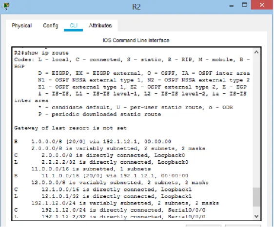
2. Configure una relación de vecino BGP entre R2 y R3. R2 ya debería estar configurado en AS2 y R3 debería estar en AS3. Anuncie las direcciones de Loopback de R3 en BGP. Codifique el ID del router R3 como 33.33.33.33. Presente el paso a con los comandos utilizados y la salida del comando show ip route.
R2(config)#
R2(config)#router bgp 2
36 Figura 8. Relación de vecino BGP entre R2 y R3
R3(config)#
R3(config)#router bgp 3
R3(config-router)#bgp router-id 33.33.33.33
R3(config-router)#neighbor 192.1.23.2 remote-as 2 R3(config-router)#network 3.0.0.0 mask 255.0.0.0
R3(config-router)#network 13.1.0.0 mask 255.255.0.0 %BGP-5-ADJCHANGE: neighbor 192.1.23.2 Up
37 Figura 9. Relación de vecino BGP entre R2 y R3
3. Configure una relación de vecino BGP entre R3 y R4. R3 ya debería estar configurado en AS3 y R4 debería estar en AS4. Anuncie las direcciones de Loopback de R4 en BGP. Codifique el ID del router R4 como 44.44.44.44. Establezca las relaciones de vecino con base en las direcciones de Loopback 0. Cree rutas estáticas para alcanzar la Loopback 0 del otro router. No anuncie la Loopback 0 en BGP. Anuncie la red Loopback de R4 en BGP. Presente el paso a con los comandos utilizados y la salida del comando show ip route.
R4#conf
Configuring from terminal, memory, or network [terminal]? ter Enter configuration commands, one per line. End with CNTL/Z. R4(config)#router b
R4(config)#router bgp 4
R4(config-router)#bgp router-id 44.44.44.44
R4(config-router)#neighbor 192.1.34.3 remote-as 3 R4(config-router)#network 4.0.0.0 mask 255.0.0.0 R4(config-router)#exit
R4(config)#ip route 3.0.0.0 255.0.0.0 192.1.34.3 R4(config)#router bgp 4
38
R4(config-router)#no network 4.0.0.0 mask 255.0.0.0 R4(config-router)#network 4.0.0.0 mask 255.0.0.0 R4(config-router)#network 14.1.0.0 mask 255.255.0.0 R4(config-router)#
R4(config-router)#exit R4(config)#exit
39 Escenario 3
Figura 11. Escenario 3
A. Configurar VTP
1. Todos los switches se configurarán para usar VTP para las actualizaciones de VLAN. El switch SWT2 se configurará como el servidor. Los switches SWT1 y SWT3 se configurarán como clientes. Los switches estarán en el dominio VPT llamado CCNP y usando la contraseña cisco.
Switch>enable Switch#conf ter
Enter configuration commands, one per line. End with CNTL/Z. Switch(config)#vtp domain CCNP
40 Switch(config)#vtp mode client
Setting device to VTP CLIENT mode. Switch(config)#vtp password cisco
Setting device VLAN database password to cisco Switch(config)#
Switch(config)#hostname SWT1 SWT1(config)#
Switch>enable
Switch#configure terminal
Enter configuration commands, one per line. End with CNTL/Z. Switch(config)#hostname SWT2
SWT2(config)#
SWT2(config)#vtp domain CCNP
Changing VTP domain name from NULL to CCNP SWT2(config)#vtp version 2
SWT2(config)#vtp mode server Device mode already VTP SERVER. SWT2(config)#vtp password cisco Setting device VLAN
Switch>ena Switch#conf
Configuring from terminal, memory, or network [terminal]? ter Enter configuration commands, one per line. End with CNTL/Z. Switch(config)#vtp domain CCNP
Changing VTP domain name from NULL to CCNP Switch(config)#vtp version 2
Switch(config)#vtp mode client
Setting device to VTP CLIENT mode. Switch(config)#vtp password cisco
Setting device VLAN database password to cisco Switch(config)#
41
2. Verifique las configuraciones mediante el comando show vtp status.
Figura 12. VTP Estatus escenario 3 SWT1
42 Figura 14. VTP Estatus escenario 3 SWT3
B. Configurar DTP (Dynamic Trunking Protocol)
1. Configure un enlace troncal ("trunk") dinámico entre SWT1 y SWT2. Debido a que el modo por defecto es dynamic auto, solo un lado del enlace debe configurarse como dynamic desirable.
SWT1#conf SWT1#configure
Configuring from terminal, memory, or network [terminal]? ter Enter configuration commands, one per line. End with CNTL/Z. SWT1(config)#interface fastEthernet 0/1
SWT1(config-if)#switchport mode dynamic desirable
SWT1(config-if)#
%LINEPROTO-5-UPDOWN: Line protocol on Interface FastEthernet0/1, changed state to up
%LINEPROTO-5-UPDOWN: Line protocol on Interface FastEthernet0/1, changed state to down
43
2. Verifique el enlace "trunk" entre SWT1 y SWT2 usando el comando show interfaces trunk.
Figura 15. Enlace TRUNK SWT1
44
3. Entre SWT1 y SWT3 configure un enlace "trunk" estático utilizando el comando switchport mode trunk en la interfaz F0/3 de SWT1
SWT1>enable
SWT1#configure terminal Enter configuration commands, one per line. End with CNTL/Z.
SWT1(config)#interface fastEthernet 0/3 SWT1(config-if)#switchport mode trunk
SWT1(config-if)#
%LINEPROTO-5-UPDOWN: Line protocol on Interface FastEthernet0/3, changed state to down
%LINEPROTO-5-UPDOWN: Line protocol on Interface FastEthernet0/3, changed state to up
4. Verifique el enlace "trunk" el comando show interfaces trunk en SWT1
Figura 17. Enlace TRUNK estático SWT1
5. Configure un enlace "trunk" permanente entre SWT2 y SWT3
SWT2# SWT2#conf
45 SWT2(config)#interface fastEthernet 0/3 SWT2(config-if)#switchport mode trunk
SWT2(config-if)#
%LINEPROTO-5-UPDOWN: Line protocol on Interface FastEthernet0/3, changed state to down
%LINEPROTO-5-UPDOWN: Line protocol on Interface FastEthernet0/3, changed state to up
SWT2(config)#exi SWT2#
SWT3# SWT3#conf
Configuring from terminal, memory, or network [terminal]? ter Enter configuration commands, one per line. End with CNTL/Z.
%LINEPROTO-5-UPDOWN: Line protocol on Interface FastEthernet0/1, changed state to down
%LINEPROTO-5-UPDOWN: Line protocol on Interface FastEthernet0/1, changed state to up
s
SWT3(config)#interface fastEthernet 0/1 SWT3(config-if)#switchport mode trunk SWT3(config-if)#exit
SWT3(config)#exit SWT3#
C. Agregar VLANs y asignar puertos.
1. En STW1 agregue la VLAN 10. En STW2 agregue las VLANS Compras (10), Mercadeo (20), Planta (30) y Admon (99)
SWT1#conf
Configuring from terminal, memory, or network [terminal]? ter Enter configuration commands, one per line. End with CNTL/Z. SWT1(config)#vlan 10
VTP VLAN configuration not allowed when device is in CLIENT mode. SWT1(config)#
SWT2# SWT2#conf
46 SWT2(config-vlan)#name Compras
SWT2(config-vlan)#vlan 20
SWT2(config-vlan)#name Mercadeo SWT2(config-vlan)#vlan 30
SWT2(config-vlan)#name Planta SWT2(config-vlan)#vlan 99 SWT2(config-vlan)#name Admon SWT2(config-vlan)#exit
SWT2(config)#
2. Verifique que las VLANs han sido agregadas correctamente SWT1(config)#vlan 10
VTP VLAN configuration not allowed when device is in CLIENT mode
SWT1: En este Swith no se pude crear la vlan 10 ya que tiene un vtp en modo cliente, lo que no deja crear la vlan de acuerdo al error indicado
47
1. Asocie los puertos a las VLAN y configure las direcciones IP de acuerdo con la siguiente tabla.
Tabla 4. Interfaces / VLAN Escenario 3.
Interfaz VLAN Direcciones IP de los PCs F0/10 VLAN 10 190.108.10.X / 24
F0/15 VLAN 20 190.108.20.X /24 F0/20 VLAN 30 190.108.30.X /24 X = número de cada PC particular
SWT1>
SWT1>enable
SWT1#configure terminal
Enter configuration commands, one per line. End with CNTL/Z. SWT1(config)#interface vlan 10
SWT1(config-if)#
%LINK-5-CHANGED: Interface Vlan10, changed state to up
%LINEPROTO-5-UPDOWN: Line protocol on Interface Vlan10, changed state to up
SWT1(config-if)#ip address 190.108.10.1 255.255.255.0 SWT1(config-if)#exit
SWT1(config)#interface vlan 20
%LINK-5-CHANGED: Interface Vlan20, changed state to up
%LINEPROTO-5-UPDOWN: Line protocol on Interface Vlan20, changed state to up
SWT1(config-if)#ip address 190.108.20.1 255.255.255.0 SWT1(config-if)#exit
SWT1(config)#interface vlan 30 SWT1(config-if)#
%LINK-5-CHANGED: Interface Vlan30, changed state to up
%LINEPROTO-5-UPDOWN: Line protocol on Interface Vlan30, changed state to up
SWT1(config-if)#ip address 190.108.30.1 255.255.255.0 SWT1(config-if)#exit
48 SWT2#
SWT2(config)#
SWT2(config)#interface vlan 10
%LINK-5-CHANGED: Interface Vlan10, changed state to up
%LINEPROTO-5-UPDOWN: Line protocol on Interface Vlan10, changed state to up
SWT2(config-if)#ip address 190.108.10.2 255.255.255.0 SWT2(config-if)#exit
SWT2(config)#interface vlan 20
%LINK-5-CHANGED: Interface Vlan20, changed state to up
%LINEPROTO-5-UPDOWN: Line protocol on Interface Vlan20, changed state to up
SWT2(config-if)#ip address 190.108.20.2 255.255.255.0 SWT2(config-if)#exit
SWT2(config)#interface vlan 30
%LINK-5-CHANGED: Interface Vlan30, changed state to up
%LINEPROTO-5-UPDOWN: Line protocol on Interface Vlan30, changed state to up
SWT2(config-if)#ip address 190.108.30.2 255.255.255.0 SWT2(config-if)#exit
SWT2(config)#
SWT3> SWT3#conf
SWT3(config)#interface vlan 10
%LINK-5-CHANGED: Interface Vlan10, changed state to up
%LINEPROTO-5-UPDOWN: Line protocol on Interface Vlan10, changed state to up
SWT3(config-if)#ip address 190.108.10.3 255.255.255.0 SWT3(config-if)#exit
SWT3(config)#interface vlan 20
%LINK-5-CHANGED: Interface Vlan20, changed state to up
%LINEPROTO-5-UPDOWN: Line protocol on Interface Vlan20, changed state to up
SWT3(config-if)#ip address 190.108.20.3 255.255.255.0 SWT3(config-if)#exit
SWT3(config)#interface vlan 30
49
%LINEPROTO-5-UPDOWN: Line protocol on Interface Vlan30, changed state to up
2. Configure el puerto F0/10 en modo de acceso para SWT1, SWT2 y SWT3 y asígnelo a la VLAN 10.
SWT1(config)#interface fastEthernet 0/10 SWT1(config-if)#switchport mode access SWT1(config-if)#switchport access vlan 10 SWT1(config-if)#exit
SWT1(config)#exit SWT1#
SWT2(config)#interface fastEthernet 0/10 SWT2(config-if)#switchport mode access SWT2(config-if)#switchport access vlan 10 SWT2(config-if)#exit
SWT2(config)#exit
SWT3(config)#interface fastEthernet 0/10 SWT3(config-if)#switchport mode access SWT3(config-if)#switchport access vlan 10 SWT3(config-if)#exit
SWT3(config)#exit SWT3#
3. Repita el procedimiento para los puertos F0/15 y F0/20 en SWT1, SWT2 y SWT3. Asigne las VLANs y las direcciones IP de los PCs de acuerdo con la tabla de arriba.
SWT1#
SWT1#configure ter
Enter configuration commands, one per line. End with CNTL/Z. SWT1(config)#interface fastEthernet 0/15
SWT1(config-if)#switchport mode access SWT1(config-if)#switchport access vlan 20 SWT1(config-if)#exit
50 SWT1(config)#exit
SWT1#
%SYS-5-CONFIG_I: Configured from console by console
SWT2# SWT2#conf
Configuring from terminal, memory, or network [terminal]? ter Enter configuration commands, one per line. End with CNTL/Z. SWT2(config)#interface fastEthernet 0/15
SWT2(config-if)#switchport mode access SWT2(config-if)#switchport access vlan 20 SWT2(config-if)#exit
SWT2(config)#interface fastEthernet 0/20 SWT2(config-if)#switchport mode access SWT2(config-if)#switchport access vlan 30 SWT2(config-if)#exi
SWT2#
%SYS-5-CONFIG_I: Configured from console by console
SWT3# SWT3#conf
Configuring from terminal, memory, or network [terminal]? ter Enter configuration commands, one per line. End with CNTL/Z. SWT3(config)#interface fastEthernet 0/15
SWT3(config-if)#switchport mode access SWT3(config-if)#switchport access vlan 20 SWT3(config-if)#exit
SWT3(config)#interface fastEthernet 0/20 SWT3(config-if)#switchport mode access SWT3(config-if)#switchport access vlan 30 SWT3(config-if)#exit
D. Configurar las direcciones IP en los Switches.
1. En cada uno de los Switches asigne una dirección IP al SVI (Switch Virtual Interface) para VLAN 99 de acuerdo con la siguiente tabla de direccionamiento y active la interfaz.
Tabla 5. SVI Switchs Escenario 3
51 SWT1#
SWT1#conf
Configuring from terminal, memory, or network [terminal]? ter Enter configuration commands, one per line. End with CNTL/Z. SWT1(config)#interface vlan 99
%LINK-5-CHANGED: Interface Vlan99, changed state to up
%LINEPROTO-5-UPDOWN: Line protocol on Interface Vlan99, changed state to up SWT1(config-if)#ip address 190.108.99.1 255.255.255.0
SWT1(config-if)#exit SWT1(config)#
SWT2# SWT2#conf
Configuring from terminal, memory, or network [terminal]? ter Enter configuration commands, one per line. End with CNTL/Z. SWT2(config)#interface vlan 99
%LINK-5-CHANGED: Interface Vlan99, changed state to up
%LINEPROTO-5-UPDOWN: Line protocol on Interface Vlan99, changed state to up
SWT2(config-if)#ip address 190.108.99.2 255.255.255.0 SWT2(config-if)#exit
SWT2(config)#
SWT3# SWT3#config
Configuring from terminal, memory, or network [terminal]? ter Enter configuration commands, one per line. End with CNTL/Z. SWT3(config)#interface vlan 99
%LINK-5-CHANGED: Interface Vlan99, changed state to up
%LINEPROTO-5-UPDOWN: Line protocol on Interface Vlan99, changed state to up
SWT3(config-if)#ip address 190.108.99.3 255.255.255.0 SWT3(config-if)#end
52
E. Verificar la conectividad Extremo a Extremo
1. Ejecute un Ping desde cada PC a los demás. Explique por qué el ping tuvo o no tuvo éxito.
Cuando el ping es realizado para equipos que estén incluidos dentro de la misma VLAN funciona sin embargo primero debe ser configurado el direccionamiento en las maquinas para realizar las pruebas de ping
2. Ejecute un Ping desde cada Switch a los demás. Explique por qué el ping tuvo o no tuvo éxito.
Para que el ping es necesario realizarlo a las direcciones ip que están incluidas y asociadas a la ip de la VLAN 99 la cual es la que permite esta conectividad entre los Swith
3. Ejecute un Ping desde cada Switch a cada PC. Explique por qué el ping tuvo o no tuvo éxito.
53
Conclusiones
Con el desarrollo de la presente actividad logramos reconocer los fundamentos aplicados a la configuración de un dispositivo dentro de una red de datos, y siendo de esta forma fundamental para su correcto funcionamiento y disponibilidad de la red. Siendo de esta Forma aplicamos todos los conceptos aprendidos dentro del diplomado de profundización Cisco CCNP donde entramos a reconocer la redistribución de rutas por ejemplo que nos proporcionan protocolos como EIGRP Y OSPF.
Configurar una interfaz de loopback para asociar esta interfaz en procesos OSPF y BGP, aseguramos que no vamos a perder las sesiones OSPF o BGP por un problema físico en la interfaz, ya que las interfaces de loopback son interfaces lógicas, siendo una técnica, aunque no muy común el aplicar estos protocolos a nuestros enrutadores nos brinda la redistribución como la queremos en nuestra red.
Ahora bien, también comprendimos la aplicabilidad de protocolos dentro de los switch siendo de esta forma que el aplicar por ejemplo redes VLAN y troncales en nuestra red es fundamental para su funcionamiento ya que esto nos proporciona una excelente seguridad en nuestra red y una reorganización que nos evita picos altos de datos y cuellos de botella en la red.
54
Referencias Bibliográficas
Teare, D., Vachon B., Graziani, R. (2015). CISCO Press (Ed). EIGRP Implementation. Implementing Cisco IP Routing (ROUTE) Foundation Learning Guide CCNP ROUTE 300-101. Recuperado de https://1drv.ms/b/s!AmIJYei-NT1IlnMfy2rhPZHwEoWx
D., Vachon B., Graziani, R. (2015). CISCO Press (Ed). OSPF Implementation. Implementing Cisco IP Routing (ROUTE) Foundation Learning Guide CCNP ROUTE 300-101. Recuperado de https://1drv.ms/b/s!AmIJYei-NT1IlnMfy2rhPZHwEoWx.
Macfarlane, J. (2014). Network Routing Basics : Understanding IP Routing in
Cisco Systems. Recuperado de
http://bibliotecavirtual.unad.edu.co:2048/login?url=http://search.ebscohost.com/ login.aspx?direct=true&db=e000xww&AN=158227&lang=es&site=ehost-live
Teare, D., Vachon B., Graziani, R. (2015). CISCO Press (Ed). Implementing a Border Gateway Protocol (BGP) Solution for ISP Connectivity. Implementing Cisco IP Routing (ROUTE) Foundation Learning Guide CCNP ROUTE 300-101. Recuperado de https://1drv.ms/b/s!AmIJYei-NT1IlnMfy2rhPZHwEoWx
Froom, R., Frahim, E. (2015). CISCO Press (Ed). Campus Network Security. Implementing Cisco IP Switched Networks (SWITCH) Foundation Learning Guide CCNP SWITCH 300-115. Recuperado de https://1drv.ms/b/s!AmIJYei-NT1IlnWR0hoMxgBNv1CJ
Lammle, T. (2010). CISCO Press (Ed). Cisco Certified Network Associate Study
Guide. Recuperado de