DIPLOMADO DE PROFUNDIZACION CISCO PRUEBA DE HABILIDADES PRÁCTICAS CCNP
JUAN RICARDO BERMEJO TIBADUISA
UNIVERSIDAD NACIONAL ABIERTA Y A DISTANCIA - UNAD
ESCUELA DE CIENCIAS BÁSICAS DE TECNOLOGÍAS E INGENIERÍA – ECBTI INGENIERÍA ELECTRÓNICA
DIPLOMADO DE PROFUNDIZACION CISCO PRUEBA DE HABILIDADES PRÁCTICAS CCNP
JUAN RICARDO BERMEJO TIBADUISA
Diplomado de opción de grado presentado para optar el título de INGENIERO ELECTRÓNICO
DIRECTOR:
MSc. GERARDO GRANADOS ACUÑA
UNIVERSIDAD NACIONAL ABIERTA Y A DISTANCIA - UNAD ESCUELA DE CIENCIAS BÁSICAS, TECNOLOGÍA E INGENIERÍA - ECBTI
INGENIERÍA ELECTRÓNICA IBAGUÉ
3
NOTA DE ACEPTACIÓN
Firma del presidente del Jurado
Firma del Jurado
Firma del Jurado
4
AGRADECIMIENTOS
Este trabajo lo dedico a mi familia, en especial a mi mamá, a mi abuelita y a mi
esposa Olga Lucia porque gracias a su apoyo e incondicional ayuda me alientan
para superarme y ser una persona integral cada día. También un agradecimiento
especial a mis amigos, compañeros de curso y a los tutores de la universidad UNAD
y del CEAD Ibagué.
5
TABLA DE CONTENIDO
Pág.
AGRADECIMIENTOS ... 4
TABLA DE CONTENIDO ... 5
LISTA DE TABLAS ... 6
LISTA DE FIGURAS ... 7
RESUMEN ... 9
ABSTRACT ... 9
INTRODUCCIÓN ... 10
DESARROLLO ... 11
Descripción de escenarios propuestos para la prueba de habilidades ... 11
Escenario 1 ... 11
Escenario 2 ... 21
CONCLUSIONES ... 46
6
LISTA DE TABLAS
Pág.
7
LISTA DE FIGURAS
Pág.
Figura 1. Escenario 1 ... 11
Figura 2. Simulación Escenario 1 ... 11
Figura 3. Configuración R1 ... 12
Figura 4. Configuración R2 ... 13
Figura 5. Configuración R3 ... 13
Figura 6. Ajuste Enlaces R1,R2,R3 ... 14
Figura 7. R2 y R3 configurar direcciones OSPFv3 ... 15
Figura 8. R3, configurar la interfaz F0/0 ... 16
Figura 9. Protocolo EIGRP ... 17
Figura 10. Interfaces pasivas ... 17
Figura 11. Asignar métricas ... 18
Figura 12. Publicidad de la Ruta ... 18
Figura 13. Publicidad de la Ruta ACL ... 19
Figura 14. Enrutamiento R1 ... 19
Figura 15. Enrutamiento R2 ... 20
Figura 16. Enrutamiento R3 ... 20
Figura 17. Verificar Comunicación - Ping ... 20
Figura 18. Verificar Comunicación ... 21
Figura 19. Verificación Final ... 21
Figura 20. Escenario 2 ... 22
Figura 21. Apagar SW ... 23
Figura 22. Apagar SW - (Simulación) ... 23
Figura 23. Nombrar SWs ... 24
Figura 24. Conexión DLS1 y DLS2 ... 25
Figura 25. Verificación Conexión utilizando LACP ... 26
Figura 26. Port - Channels ... 27
Figura 27. Port - Channels ALS2 ... 28
Figura 28. Port - Channels en las Interfaces ... 29
Figura 29. Dominio UNAD ... 31
Figura 30. Dominio UNAD - ALS1 ... 31
Figura 31. Configurar DLS1 – VLAN ... 32
Figura 32. ALS1 y ALS 2 Como Clientes ... 33
Figura 33. Configurar servidor ... 35
Figura 34. Configuración Servidor Principal ... 35
Figura 35. DLS1 Suspender VLAN 434 ... 36
Figura 36. Modo VPT Transparente ... 36
8
Figura 38. VLAN 567 Contabilidad ... 37
Figura 39. Configurar DLS1- Spanning tree ... 38
Figura 40. Configurar DLS2 - Spanning tree ... 38
Figura 41. Configurar Puertos Troncales ... 39
Figura 42. Puertos Troncales DLS2 ... 39
Figura 43. Interfaces como puertos de Acceso ... 40
Figura 44. Interfaces Puertos de Acceso ALS1 ... 41
Figura 45. Interfaces Puertos Acceso ALS2 ... 41
Figura 46. Verificar la Existencia - VLANs ... 42
Figura 47. Verificar la Existencia - VLANs ALS1 ... 42
Figura 48. VLANs Correctas ... 43
Figura 49. Verificar VLANs Correctas ... 43
Figura 50. VLANs Correctas – Puertos Troncales - Acceso ... 44
Figura 51. EtherChannel DLS1 y ALS1 - Correcto ... 44
Figura 52. Configuración Spanning tree DLS1 y DLS2 ... 45
9 RESUMEN
El desarrollo de la “Prueba de habilidades prácticas”, es la actividad final para concretar conocimientos adquiridos en el Diplomado de Profundización CCNP, donde nos ponemos a prueba manejando un entorno de simulación y programación reflejando destrezas en la implementación de protocolos de enrutamiento como lo son EIGRP, OSPF, BGP, redistribución de rutas, Dynamic Multi VPN, VRF Lite y protocolos en IPv6, VLANs y troncales, Spanning Tree, entre otros.
Palabras clave: CCNP, Simulación, Enrutamiento, IPv6.
ABSTRACT
HHG The development of the "Practical skills test" is the final activity to concretize knowledge acquired in the CCNP Deepening Diploma, where we test ourselves by managing a simulation and programming environment reflecting skills in the implementation of routing protocols such as EIGRP, OSPF, BGP, route redistribution, Dynamic Multi VPN, VRF Lite and protocols in IPv6, VLAN and trunks, Spanning Tree, among others.
10
INTRODUCCIÓN
El curso Profundización CCNP (Cisco Certified Network Professional) como opción de grado en Ingeniería Electrónica busca identificar el grado de desarrollo de competencias y habilidades que fueron adquiridas a lo largo del diplomado. Lo esencial es poner a prueba los niveles de comprensión y solución de problemas relacionados con diversos aspectos de Networking.
11 DESARROLLO
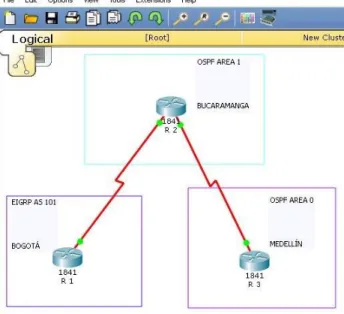
Descripción de escenarios propuestos para la prueba de habilidades Escenario 1
Una empresa de confecciones posee tres sucursales distribuidas en las ciudades de Bogotá, Medellín y Bucaramanga, en donde el estudiante será el administrador de la red, el cual deberá configurar e interconectar entre sí cada uno de los dispositivos que forman parte del escenario, acorde con los lineamientos establecidos para el direccionamiento IP, protocolos de enrutamiento y demás aspectos que forman parte de la topología de red.
Topología de red
Figura 1. Escenario 1
12
Parte 1: Configuración del escenario propuesto
1. Configurar las interfaces con las direcciones IPv4 e IPv6 que se muestran en la topología de red.
Configuraciones iniciales: Se adjunta código y pantallazos con veracidad del código Router>
Router>
Router>enable
Router# configure terminal
Enter configuration commands, one per line. End with CNTL/Z. Router(config)# hostname R1
R1(config)# interface serial 0/0/0
R1(config-if)# ip address 192.168.9.1 255 255 255 252 % Invalid input detected at '^' marker.
R1(config-if)# ip address 192.168.9.1 255.255.255.252 R1(config-if)# ipv6 address 2001:DB8:ACAD:90::1/64 R1(config-if)# clock rate 128000
R1(config-if)# no shutdown R1(config-if)# exit
R1(config)# interface giga 0/0
R1(config-if)# ip address 192.168.110.1 255.255.255.0 R1(config-if)# ipv6 address 2001:DB8:ACAD:110::1/64 R1(config-if)# no shutdown
R1(config-if)#
13
Figura 4. Configuración R2
14
2. Ajustar el ancho de banda a 128 kbps sobre cada uno de los enlaces seriales ubicados en R1, R2, y R3 y ajustar la velocidad de reloj de las conexiones de DCE según sea apropiado.
Figura 6. Ajuste Enlaces R1,R2,R3
3. En R2 y R3 configurar las familias de direcciones OSPFv3 para IPv4 e IPv6. Utilice el identificador de enrutamiento 2.2.2.2 en R2 y 3.3.3.3 en R3 para ambas familias de direcciones.
R2(config-if)#exit
R2(config)# router ospf 1
R2(config-router)# router-id 2.2.2.2
R2(config-router)# reload or use "clear ip ospf process" R2(config-router)# exit
R2(config)# ipv6 unicast-routing R2(config)# ipv6 router ospf 1 R2(config-rtr)# router-id 2.2.2.2 R2(config-rtr)#
15
Figura 7. R2 y R3 configurar direcciones OSPFv3
4. En R2, configurar la interfaz F0/0 en el área 1 de OSPF y la conexión serial entre R2 y R3 en OSPF área 0.
R2>Enable
R2# configure terminal
Enter configuration commands, one per line. End with CNTL/Z. R2(config)# router ospf 1
R2(config-router)# network 192.168.9.0 0.0.0.3 area 0 R2(config-router)#
R2(config-router)# 01:11:33: %ospf-6-areachg: 192.168.9.0/0 changed from area 1 to area 0
% Invalid input detected at '^' marker. R2(config-router)#
R2(config-router)# network 192.168.2.0 0.0.0.255 area 1 R2(config-router)# network 192.168.9.4 0.0.0.3 area 0 R2(config-router)# ipv6 unicast-routing
R2(config)# ipv6 router ospf 1 R2(config-rtr)# router-id 2.2.2.2 R2(config-rtr)# exit
R2(config)# interface Fast 0/0 R2(config-if)# ipv6 ospf 1 area 1 R2(config-if)# no shutdown R2(config-if)# exit
16 R2(config-if)#exit
R2(config)#
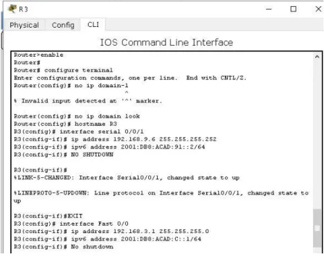
5. En R3, configurar la interfaz F0/0 y la conexión serial entre R2 y R3 en OSPF área 0.
Figura 8. R3, configurar la interfaz F0/0
6. Configurar el área 1 como un área totalmente Stubby.
7. Propagar rutas por defecto de IPv4 y IPv6 en R3 al interior del dominio OSPFv3. Nota: Es importante tener en cuenta que una ruta por defecto es diferente a la definición de rutas estáticas.
R3>enable R3#configure t
Enter configuration commands, one per line. End with CNTL/Z. R3(config)#
R3(config)# ipv6 route ::/0 2001:DB8:ACAD:91:: R3(config)# ipv6 router ospf 1
R3(config-rtr)# default-information originate R3(config-rtr)# end
R3#
17
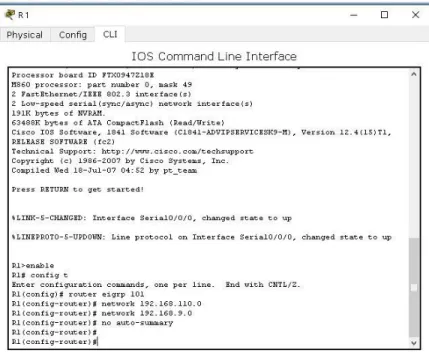
8. Realizar la configuración del protocolo EIGRP para IPv4 como IPv6. Configurar la interfaz F0/0 de R1 y la conexión entre R1 y R2 para EIGRP con el sistema autónomo 101. Asegúrese de que el resumen automático está desactivado.
Figura 9. Protocolo EIGRP
18
10. En R2, configurar la redistribución mutua entre OSPF y EIGRP para IPv4 e IPv6. Asignar métricas apropiadas cuando sea necesario.
Figura 11. Asignar métricas
11. En R2, de hacer publicidad de la ruta 192.168.3.0/24 a R1 mediante una lista de distribución y ACL.
19
Figura 13. Publicidad de la Ruta ACL
Parte 2: Verificar conectividad de red y control de la trayectoria.
a. Registrar las tablas de enrutamiento en cada uno de los routers, acorde con los parámetros de configuración establecidos en el escenario propuesto.
20
Figura 15. Enrutamiento R2
Figura 16. Enrutamiento R3
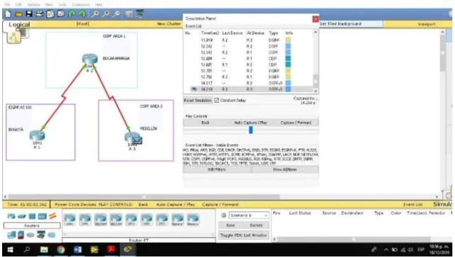
b. Verificar comunicación entre routers mediante el comando ping y traceroute
21
Figura 18. Verificar Comunicación
c. Verificar que las rutas filtradas no están presentes en las tablas de enrutamiento de los routers correctas.
Figura 19. Verificación Final
Escenario 2
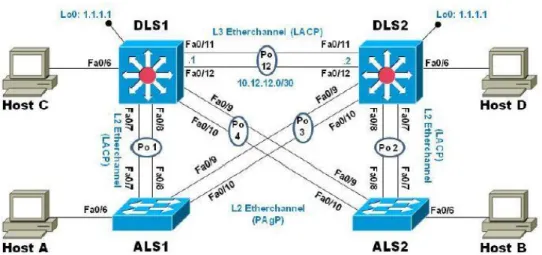
Una empresa de comunicaciones presenta una estructura Core acorde a la topología de red, en donde el estudiante será el administrador de la red, el cual deberá configurar e interconectar entre sí cada uno de los dispositivos que forman parte del escenario, acorde con los lineamientos establecidos para el direccionamiento IP, etherchannels, VLANs y demás aspectos que forman parte del escenario propuesto.
22
Figura 20. Escenario 2
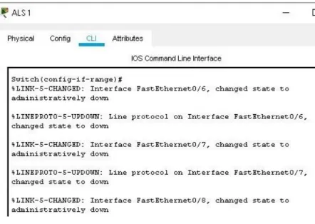
Parte 1: Configurar la red de acuerdo con las especificaciones. a) Apagar todas las interfaces en cada switch.
b) Asignar un nombre a cada switch acorde al escenario establecido. Switch>enable
Switch#configure t
Enter configuration commands, one per line. End with CNTL/Z. Switch(config)# hostname ALS 1
% Invalid input detected at '^' marker. Switch(config)# hostname ALS1 ALS1(config)#
Switch>ENABLE
Switch#configure terminal
Enter configuration commands, one per line. End with CNTL/Z. Switch(config)# hostname ALS2
ALS2(config)# ALS2(config)#
Switch>ENABLE
Switch#CONFIGURE T
Enter configuration commands, one per line. End with CNTL/Z. Switch(config)# DLS1
23
Figura 21. Apagar SW
24
Figura 23. Nombrar SWs
c) Configurar los puertos troncales y Port-channels tal como se muestra en el diagrama.
1) La conexión entre DLS1 y DLS2 será un EtherChannel capa-3 utilizando LACP. Para DLS1 se utilizará la dirección IP 10.12.12.1/30 y para DLS2 utilizará 10.12.12.2/30.
DLS1>enable
DLS1# configure terminal
Enter configuration commands, one per line. End with CNTL/Z. DLS1(config)# interface port-channel 12
DLS1(config-if)# no switchport
DLS1(config-if)# ip address 10.12.12.1 255.255.255.252 DLS1(config-if)# exit
DLS1(config)# interface range Fast 0/11-12 DLS1(config-if-range)# no switchport
DLS1(config-if-range)# channel-group 12 mode active DLS1(config-if-range)# exit
DLS1(config)# exit DLS1#
%SYS-5-CONFIG_I: Configured from console by console
DLS2>enable
DLS2#config terminal
Enter configuration commands, one per line. End with CNTL/Z. DLS2(config)# interface port-channel 12
DLS2(config-if)# no switchport
DLS2(config-if)# ip address 10.12.12.2 255.255.255.252 DLS2(config-if)# exit
DLS2(config)# interface range Fast 0/11-12 DLS2(config-if-range)# no switchport
25 DLS2(config-if-range)# exit
DLS2(config)# exit DLS2#
%SYS-5-CONFIG_I: Configured from console by console
DLS2# show Etherchannel summary Flags: D - down P - in port-channel I - stand-alone s - suspended H - Hot-standby (LACP only) R - Layer3 S - Layer2
U - in use f - failed to allocate aggregator u - unsuitable for bundling
w - waiting to be aggregated d - default port
Number of channel-groups in use: 1 Number of aggregators: 1
Group Port-channel Protocol Ports
---+---+---+---
12 Po12(RD) LACP Fa0/11(D) Fa0/12(D) DLS2#
26
Figura 25. Verificación Conexión utilizando LACP
2) Los Port-channels en las interfaces Fa0/7 y Fa0/8 utilizarán LACP. DLS1#enable
DLS1#configure t
Enter configuration commands, one per line. End with CNTL/Z. DLS1(config)#
DLS1(config)#interface range Fast0/7-8
DLS1(config-if-range)# switchport mode Trunk
Command rejected: An interface whose trunk encapsulation is "Auto" can not be configured to "trunk" mode.
Command rejected: An interface whose trunk encapsulation is "Auto" can not be configured to "trunk" mode.
DLS1(config-if-range)#
DLS1(config-if-range)# switchport Trunk encapsulation dot1q DLS1(config-if-range)# switchport mode Trunk
DLS1(config-if-range)# Channel-group 1 mode active DLS1(config-if-range)#
Creating a port-channel interface Port-channel 1
DLS1(config-if-range)# no shutdown
%LINK-5-CHANGED: Interface FastEthernet0/7, changed state to down
27 DLS1(config-if-range)#
DLS1(config-if-range)#exit DLS1(config)#exit
DLS1#
%SYS-5-CONFIG_I: Configured from console by console
DLS1# show etherchannel summary Flags: D - down P - in port-channel I - stand-alone s - suspended H - Hot-standby (LACP only) R - Layer3 S - Layer2
U - in use f - failed to allocate aggregator u - unsuitable for bundling
w - waiting to be aggregated d - default port
Number of channel-groups in use: 2 Number of aggregators: 2
Group Port-channel Protocol Ports
---+---+---+--- 1 Po1(SD) LACP Fa0/7(D) Fa0/8(D)
12 Po12(RD) LACP Fa0/11(D) Fa0/12(D) DLS1#
28
Figura 27. Port - Channels ALS2
3) Los Port-channels en las interfaces F0/9 y fa0/10 utilizará PAgP.
DLS1# configure t
Enter configuration commands, one per line. End with CNTL/Z. DLS1(config)# interface range Fast 0/9-10
DLS1(config-if-range)# switchport trunk encapsulation dot1q DLS1(config-if-range)# switchport mode trunk
DLS1(config-if-range)# channel-group 4 mode desirable DLS1(config-if-range)#
Creating a port-channel interface Port-channel 4
DLS1(config-if-range)# no shutdown
%LINK-5-CHANGED: Interface FastEthernet0/9, changed state to down
%LINK-5-CHANGED: Interface FastEthernet0/10, changed state to down DLS1(config-if-range)#
DLS1(config-if-range)#exit DLS1(config)#exit
DLS1#
%SYS-5-CONFIG_I: Configured from console by console
29 Flags: D - down P - in port-channel
I - stand-alone s - suspended H - Hot-standby (LACP only) R - Layer3 S - Layer2
U - in use f - failed to allocate aggregator u - unsuitable for bundling
w - waiting to be aggregated d - default port
Number of channel-groups in use: 3 Number of aggregators: 3
Group Port-channel Protocol Ports
---+---+---+---
1 Po1(SU) LACP Fa0/7(P) Fa0/8(P) 4 Po4(SD) PAgP Fa0/9(D) Fa0/10(D) 12 Po12(RD) LACP Fa0/11(D) Fa0/12(D) DLS1#
30
4) Todos los puertos troncales serán asignados a la VLAN 800 como la VLAN nativa.
DLS1>enable
DLS1#configure terminal
Enter configuration commands, one per line. End with CNTL/Z. DLS1(config)# interface Po1
DLS1(config-if)# switchport trunk native vlan 800 DLS1(config-if)# exit
DLS1(config)# interface po4
DLS1(config-if)# switchport trunk native vlan 800 DLS1(config-if)# exit
DLS1(config)#
d) Configurar DLS1, ALS1, y ALS2 para utilizar VTP versión 3
1) Utilizar el nombre de dominio UNAD con la contraseña cisco123
DLS1>enable
DLS1#configure terminal
Enter configuration commands, one per line. End with CNTL/Z. DLS1(config)# vpt domain UNAD
% Invalid input detected at '^' marker. DLS1(config)# vtp domain UNAD
Changing VTP domain name from NULL to UNAD DLS1(config)# vtp pass cisco123
Setting device VLAN database password to cisco123 DLS1(config)# vtp version 3
% Invalid input detected at '^' marker. DLS1(config)# vtp version 2
DLS1(config)# exit DLS1#
31
Figura 29. Dominio UNAD
32
2) Configurar DLS1 como servidor principal para las VLAN.
DLS1>enable
DLS1#configure terminal
Enter configuration commands, one per line. End with CNTL/Z. DLS1(config)# vtp mode server
Device mode already VTP SERVER. DLS1(config)#
DLS1(config)# exit DLS1#
%SYS-5-CONFIG_I: Configured from console by console DLS1# show vtp status
VTP Version capable : 1 to 2 VTP version running : 2 VTP Domain Name : UNAD VTP Pruning Mode : Disabled VTP Traps Generation : Disabled Device ID : 0000.0C91.4BA0
Configuration last modified by 0.0.0.0 at 3-1-93 03:47:11 Local updater ID is 0.0.0.0 (no valid interface found) Feature VLAN :
---
VTP Operating Mode : Server
Maximum VLANs supported locally : 1005 Number of existing VLANs : 5
Configuration Revision : 3
MD5 digest : 0xAC 0xE4 0x38 0xC1 0xA1 0xBF 0x65 0x0A 0x55 0x39 0x76 0x2C 0x15 0xA6 0x40 0xC6
DLS1#
33
3) Configurar ALS1 y ALS2 como clientes VTP.
ALS1>enable
ALS1#configure terminal
Enter configuration commands, one per line. End with CNTL/Z. ALS1(config)# vtp mode client
Setting device to VTP CLIENT mode. ALS1(config)# exit
ALS1#
%SYS-5-CONFIG_I: Configured from console by console
ALS1#show vtp status VTP Version : 2
Configuration Revision : 3
Maximum VLANs supported locally : 255 Number of existing VLANs : 5
VTP Operating Mode : Client VTP Domain Name : UNAD VTP Pruning Mode : Disabled VTP V2 Mode : Disabled
VTP Traps Generation : Disabled
MD5 digest : 0xAC 0xE4 0x38 0xC1 0xA1 0xBF 0x65 0x0A Configuration last modified by 0.0.0.0 at 3-1-93 03:47:11
34
e) Configurar en el servidor principal las siguientes VLAN: Tabla 1. Configurar VLAN
Número de VLAN Nombre de VLAN Número de VLAN Nombre de VLAN
800 NATIVA 434 ESTACIONAMIENTO
12 EJECUTIVOS 123 MANTENIMIENTO
234 HUESPEDES 1010 VOZ
1111 VIDEONET 3456 ADMINISTRACIÓN
DLS1#
DLS1#configure terminal
Enter configuration commands, one per line. End with CNTL/Z. DLS1(config)# vlan 800
DLS1(config-vlan)# name NATIVA DLS1(config-vlan)# VLAN 12
DLS1(config-vlan)# Name EJECUTIVOS DLS1(config-vlan)# vlan 234
DLS1(config-vlan)# name HUESPEDES DLS1(config-vlan)# vlan 1111
VLAN_CREATE_FAIL: Failed to create VLANs 1111 : extended VLAN(s) not allowed in current VTP mode
DLS1(config)# vlan 1 1 1 1
% Invalid input detected at '^' marker. DLS1(config)# vlan 111
DLS1(config-vlan)# name VIDEONET DLS1(config-vlan)# VLAN 34
DLS1(config-vlan)# name ESTACIONAMIENTO DLS1(config-vlan)# Vlan 123
DLS1(config-vlan)# name MANTENIMIENTO DLS1(config-vlan)# vlan 101
DLS1(config-vlan)# name VOZ DLS1(config-vlan)# vlan 3456
VLAN_CREATE_FAIL: Failed to create VLANs 3456 : extended VLAN(s) not allowed in current VTP mode
DLS1(config)# vlan 345
35
Figura 33. Configurar servidor
36 f) En DLS1, suspender la VLAN 434.
Figura 35. DLS1 Suspender VLAN 434
g) Configurar DLS2 en modo VTP transparente VTP utilizando VTP versión 2, y configurar en DLS2 las mismas VLAN que en DLS1.
DLS2>enable
DLS2#configure terminal
Enter configuration commands, one per line. End with CNTL/Z. DLS2(config)# vtp mode transparent
Setting device to VTP TRANSPARENT mode. DLS2(config)# exit
DLS2#
37
h) Suspender VLAN 434 en DLS2.
Figura 37. DLS2 Suspender VLAN
i) En DLS2, crear VLAN 567 con el nombre de CONTABILIDAD. La VLAN de CONTABILIDAD no podrá estar disponible en cualquier otro Switch de la red. DLS2(config-vlan)#
DLS2(config-vlan)# DLS2(config-vlan)#exit
DLS2(config)# interface port-channel 2
DLS2(config-if)# switchport trunk allowed vlan except 567 DLS2(config-if)# exit
DLS2(config)# interface port-channel 3
DLS2(config-if)# switchport trunk allowed vlan except 567 DLS2(config-if)# exit
DLS2(config)#
38
j) Configurar DLS1 como Spanning tree root para las VLAN 1, 12, 434, 800, 1010, 1111 y 3456 y como raíz secundaria para las VLAN 123 y 234.
DLS1>enable
DLS1# configure terminal
Enter configuration commands, one per line. End with CNTL/Z.
DLS1(config)# spanning-tree vlan 1,12,434,800,101,111,345 root primary DLS1(config)# spanning-tree vlan 123,234 root secondary
DLS1(config)# exit DLS1#
Figura 39. Configurar DLS1- Spanning tree
k) Configurar DLS2 como Spanning tree root para las VLAN 123 y 234 y como una raíz secundaria para las VLAN 12, 434, 800, 1010, 1111 y 3456.
Figura 40. Configurar DLS2 - Spanning tree
l) Configurar todos los puertos como troncales de tal forma que solamente las VLAN que se han creado se les permitirá circular a través de estos puertos. ALS1>enable
ALS1# configure t
Enter configuration commands, one per line. End with CNTL/Z. ALS1(config)# interface fastethernet0/1
ALS1(config-if)# switchport mode trunk
39
ALS1(config-if)# switchport trunk allowed vlan 12,234,111,434,123,101,345 ALS1(config-if)#
ALS1(config-if)#exit ALS1(config)#
Figura 41. Configurar Puertos Troncales
40
m) Configurar las siguientes interfaces como puertos de acceso, asignados a las VLAN de la siguiente manera:
Tabla 2. Interfaces VLAN
Interfaz DLS1 DLS2 ALS1 ALS2
Interfaz Fa0/6 3456 12 , 1010 123, 1010 234
Interfaz Fa0/15 1111 1111 1111 1111
Interfaces F0 /16-18 567 DLS1>
DLS1> enable
DLS1# configure terminal
Enter configuration commands, one per line. End with CNTL/Z. DLS1(config)# interface Fast0/6
DLS1(config-if)# switchport access vlan 3456 % Access VLAN does not exist. Creating vlan 3456 DLS1(config-if)# switchport access vlan 345
DLS1(config-if)# spanning-tree portfast
%Warning: portfast should only be enabled on ports connected to a single host. Connecting hubs, concentrators, switches, bridges, etc... to this interface when portfast is enabled, can cause temporary bridging loops. Use with CAUTION
%Portfast has been configured on FastEthernet0/6 but will only have effect when the interface is in a non-trunking mode. DLS1(config-if)#no shut
41
Figura 44. Interfaces Puertos de Acceso ALS1
42
Parte 2: conectividad de red de prueba y las opciones configuradas. a. Verificar la existencia de las VLAN correctas en todos los switches y la
asignación de puertos troncales y de acceso
Figura 46. Verificar la Existencia - VLANs
43
Figura 48. VLANs Correctas
44
Figura 50. VLANs Correctas – Puertos Troncales - Acceso
b. Verificar que el EtherChannel entre DLS1 y ALS1 está configurado correctamente
45
c. Verificar la configuración de Spanning tree entre DLS1 o DLS2 para cada VLAN.
Figura 52. Configuración Spanning tree DLS1 y DLS2
46
CONCLUSIONES
La prueba de habilidades CCNP fue importante en el uso de comandos IOS de configuración avanzada en routers (con direccionamiento IPv4 e IPv6) para protocolos de enrutamiento como: RIPng, OSPFv3, EIGRP y BGP, en entornos de direccionamiento sin clase, con lo que se logró diseñar e implementar soluciones de red escalables, mediante el uso de los principios de enrutamiento y conmutación de paquetes en ambientes LAN y WAN.
Con la configuración adecuada de plataformas de conmutación basadas en switches, mediante el uso de protocolos como STP y la configuración de VLANs en escenarios de red corporativos, se comprende el modo de operación de las subredes y los beneficios de administrar dominios de broadcast independientes, en múltiples escenarios al interior de una red jerárquica convergente.
47
BIBLIOGRAFÍA
Teare, D., Vachon B., Graziani, R. (2015). CISCO Press (Ed). Basic Network and
Routing Concepts. Implementing Cisco IP Routing (ROUTE) Foundation Learning
Guide CCNP ROUTE 300-101. Recuperado de https://1drv.ms/b/s!AmIJYei- NT1IlnMfy2rhPZHwEoWx
Teare, D., Vachon B., Graziani, R. (2015). CISCO Press (Ed). EIGRP Implementation. Implementing Cisco IP Routing (ROUTE) Foundation Learning Guide CCNP ROUTE 300-101. Recuperado de https://1drv.ms/b/s!AmIJYei-
NT1IlnMfy2rhPZHwEoWx
Teare, D., Vachon B., Graziani, R. (2015). CISCO Press (Ed). Path Control Implementation. Implementing Cisco IP Routing (ROUTE) Foundation Learning
Guide CCNP ROUTE 300-101. Recuperado de https://1drv.ms/b/s!AmIJYei- NT1IlnMfy2rhPZHwEoWx
Teare, D., Vachon B., Graziani, R. (2015). CISCO Press (Ed). Implementing IPv6 in the Enterprise Network. Implementing Cisco IP Routing (ROUTE) Foundation Learning Guide CCNP ROUTE 300-101. Recuperado de https://1drv.ms/b/s!AmIJYei-NT1IlnMfy2rhPZHwEoWx