1
DIPLOMADO DE PROFUNDIZACIÓN CISCO
DISEÑO E IMPLEMENTACIÓN DE SOLUCIONES INTEGRADAS LAN / WAN
EVALUACIÓN – PRUEBA DE HABILIDADES PRÁCTICAS CCNA
Elaborado Por:
JAIRO ENRIQUE GÓMEZ GÓMEZ C.C: 1052393641
ESCUELA DE CIENCIAS BASICAS TECNOLOGIA E INGENIERIA UNIVERSIDAD NACIONAL ABIERTA Y A DITANCIA UNAD
2
DIPLOMADO DE PROFUNDIZACIÓN CISCO
DISEÑO E IMPLEMENTACIÓN DE SOLUCIONES INTEGRADAS LAN / WAN
EVALUACIÓN – PRUEBA DE HABILIDADES PRÁCTICAS CCNA
Elaborado Por:
JAIRO ENRIQUE GÓMEZ GÓMEZ C.C: 1052393641
Presentado A:
GERARDO GRANADOS ACUÑA
ESCUELA DE CIENCIAS BASICAS TECNOLOGIA E INGENIERIA UNIVERSIDAD NACIONAL ABIERTA Y A DITANCIA UNAD
3
NOTA DE ACEPTACION
______________________________ ______________________________ ______________________________ ______________________________ ______________________________ ______________________________ ______________________________
______________________________ Presidente del jurado
______________________________ Jurado
______________________________ Jurado
4 Contenido
INTRODUCCIÓN ...6
DESARROLLO ESCENEARIO 1 ...7
Tabla de direccionamiento ...7
Tabla de asignación de VLAN y de puertos ...8
Tabla de enlaces troncales ...8
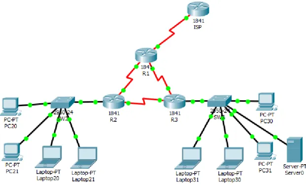
Situación ...8
Solución ...9
1. SW1 VLAN y las asignaciones de puertos de VLAN deben cumplir con la tabla 1. 9 2. Los puertos de red que no se utilizan se deben deshabilitar. ...9
3. La información de dirección IP R1, R2 y R3 debe cumplir con la tabla 1. ... 14
4. Laptop20, Laptop21, PC20, PC21, Laptop30, Laptop31, PC30 y PC31 deben obtener información IPv4 del servidor DHCP. ... 19
5. R1 debe realizar una NAT con sobrecarga sobre una dirección IPv4 pública. Asegúrese de que todos los terminales pueden comunicarse con Internet pública (haga ping a la dirección ISP) y la lista de acceso estándar se llama INSIDE-DEVS. 19 6. R1 debe tener una ruta estática predeterminada al ISP que se configuró y que incluye esa ruta en el dominio RIPv2. ... 20
7. R2 es un servidor de DHCP para los dispositivos conectados al puerto FastEthernet0/0. ... 22
8. R2 debe, además de enrutamiento a otras partes de la red, ruta entre las VLAN 100 y 200. ... 22
9. El Servidor0 es sólo un servidor IPv6 y solo debe ser accesibles para los dispositivos en R3 (ping). ... 22
10. La NIC instalado en direcciones IPv4 e IPv6 de Laptop30, de Laptop31, de PC30 y obligación de configurados PC31 simultáneas (dual-stack). Las direcciones se deben configurar mediante DHCP y DHCPv6... 23
11. La interfaz FastEthernet 0/0 del R3 también deben tener direcciones IPv4 e IPv6 configuradas (dual- stack). ... 23
12. R1, R2 y R3 intercambian información de routing mediante RIP versión 2. ... 24
5
14. Verifique la conectividad. Todos los terminales deben poder hacer ping entre sí y a la dirección IP del ISP. Los terminales bajo el R3 deberían poder hacer IPv6-ping
entre ellos y el servidor. ... 24
DESARROLLO ESCENARIO 2 ... 26
Escenario: ... 26
Solución ... 27
1. Configurar el direccionamiento IP acorde con la topología de red para cada uno de los dispositivos que forman parte del escenario ... 28
2. Configurar el protocolo de enrutamiento OSPFv2 bajo los siguientes criterios: ... 33
3. Configurar VLANs, Puertos troncales, puertos de acceso, encapsulamiento, Inter-VLAN Routing y Seguridad en los Switches acorde a la topología de red establecida. ... 39
4. En el Switch 3 deshabilitar DNS lookup ... 42
5. Asignar direcciones IP a los Switches acorde a los lineamientos. ... 43
6. Desactivar todas las interfaces que no sean utilizadas en el esquema de red. ... 43
7. Implement DHCP and NAT for IPv4 ... 43
8. Configurar R1 como servidor DHCP para las VLANs 30 y 40. ... 43
9. Reservar las primeras 30 direcciones IP de las VLAN 30 y 40 para configuraciones estáticas. ... 43
10. Configurar NAT en R2 para permitir que los host puedan salir a internet ... 44
11. Configurar al menos dos listas de acceso de tipo estándar a su criterio en para restringir o permitir tráfico desde R1 o R3 hacia R2. ... 44
12. Configurar al menos dos listas de acceso de tipo extendido o nombradas a su criterio en para restringir o permitir tráfico desde R1 o R3 hacia R2. ... 45
13. Verificar procesos de comunicación y redireccionamiento de tráfico en los routers mediante el uso de Ping y Traceroute. ... 45
CONCLUSIONES ... 46
6
INTRODUCCIÓN
Sin lugar a duda la importancia de las telecomunicaciones en nuestro tiempo ha ido avanzando a pasos agigantados y vemos gran interés, lo que hace lograr una gran expansión en este ámbito, además de la mano de una empresa como Cisco Systems que es el líder mundial en redes para Internet, se ha permitido avanzar aún más en el área de las telecomunicaciones, es por esto que en asocio con la Universidad Nacional Abierta y a Distancia UNAD, se pretende dar una
herramienta adicional en el ámbito profesional a los estudiantes que obtén por la realización del diplomado de profundización cisco (diseño e implementación de soluciones integradas LAN / WAN).
La evaluación denominada “Prueba de habilidades prácticas”, forma parte de las actividades evaluativas del Diplomado de Profundización CCNA, la cual busca identificar el grado de desarrollo de competencias y habilidades que fueron adquiridas a lo largo del diplomado. Lo esencial es poner a prueba los niveles de comprensión y solución de problemas relacionados con diversos aspectos de Networking.
7
DESARROLLO ESCENEARIO 1
Tabla de direccionamiento
El
administrador Interfaces Dirección IP Máscara de subred
Gateway predeterminado
ISP S0/0/0 200.123.211.1 255.255.255.0 N/D
R1
Se0/0/0 200.123.211.2 255.255.255.0 N/D
Se0/1/0 10.0.0.1 255.255.255.252 N/D
Se0/1/1 10.0.0.5 255.255.255.252 N/D
R2
Fa0/0,100 192.168.20.1 255.255.255.0 N/D Fa0/0,200 192.168.21.1 255.255.255.0 N/D
Se0/0/0 10.0.0.2 255.255.255.252 N/D
Se0/0/1 10.0.0.9 255.255.255.252 N/D
R3 Fa0/0
192.168.30.1 255.255.255.0 N/D
2001:db8:130::9C0:80F:301 /64 N/D
Se0/0/0 10.0.0.6 255.255.255.252 N/D
Se0/0/1 10.0.0.10 255.255.255.252 N/D
8
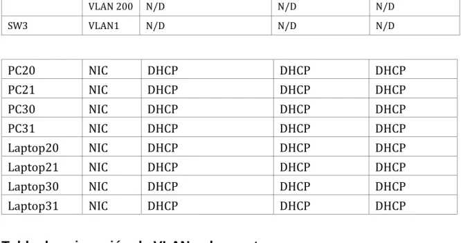
VLAN 200 N/D N/D N/D
SW3 VLAN1 N/D N/D N/D
PC20 NIC DHCP DHCP DHCP
PC21 NIC DHCP DHCP DHCP
PC30 NIC DHCP DHCP DHCP
PC31 NIC DHCP DHCP DHCP
Laptop20 NIC DHCP DHCP DHCP
Laptop21 NIC DHCP DHCP DHCP
Laptop30 NIC DHCP DHCP DHCP
Laptop31 NIC DHCP DHCP DHCP
Tabla de asignación de VLAN y de puertos
Dispositivo VLAN Nombre Interfaz
SW2 100 LAPTOPS Fa0/2-3
SW2 200 DESTOPS Fa0/4-5
SW3 1 - Todas las interfaces
Tabla de enlaces troncales
Dispositivo
local Interfaz local Dispositivo remoto
SW2 Fa0/2-3 100
Situación
9 Solución
1. SW1 VLAN y las asignaciones de puertos de VLAN deben cumplir con la tabla 1.
2. Los puertos de red que no se utilizan se deben deshabilitar.
Dispositivo VLAN Nombre Interfaz
SW3 1 - Todas las interfaces
El el SW3 configuramos la vlan 1 y asignamos todos los puertos a la misma
SW3#conf t
Enter configuration commands, one per line. End with CNTL/Z. SW3(config)#vlan 1
SW3(config-vlan)#exit
SW3(config)#interface vlan 1 SW3(config-if)#ex
SW3(config)#in
SW3(config)#interface range fastEthernet 0/1-24 SW3(config-if-range)#switchport access vlan 1 SW3(config-if-range)#ex
SW3(config)#ex SW3#
%SYS-5-CONFIG_I: Configured from console by console SW3#show vlan
VLAN Name Status Ports
---- --- --- ---
1 default active Fa0/1, Fa0/2, Fa0/3, Fa0/4
Fa0/5, Fa0/6, Fa0/7, Fa0/8
Fa0/9, Fa0/10, Fa0/11, Fa0/12
10
Fa0/17, Fa0/18, Fa0/19, Fa0/20
Fa0/21, Fa0/22, Fa0/23, Fa0/24
Deshabilitamos los puertos que no se van a usar en el SW2
SW3(config)#interface range fastEthernet 0/6-23 SW3(config-if-range)#sh
SW3(config-if-range)#shutdown
%LINK-5-CHANGED: Interface FastEthernet0/6, changed state to administratively down
%LINK-5-CHANGED: Interface FastEthernet0/7, changed state to administratively down
%LINK-5-CHANGED: Interface FastEthernet0/8, changed state to administratively down
%LINK-5-CHANGED: Interface FastEthernet0/9, changed state to administratively down
%LINK-5-CHANGED: Interface FastEthernet0/10, changed state to administratively down
%LINK-5-CHANGED: Interface FastEthernet0/11, changed state to administratively down
%LINK-5-CHANGED: Interface FastEthernet0/12, changed state to administratively down
%LINK-5-CHANGED: Interface FastEthernet0/13, changed state to administratively down
%LINK-5-CHANGED: Interface FastEthernet0/14, changed state to administratively down
%LINK-5-CHANGED: Interface FastEthernet0/15, changed state to administratively down
11
%LINK-5-CHANGED: Interface FastEthernet0/17, changed state to administratively down
%LINK-5-CHANGED: Interface FastEthernet0/18, changed state to administratively down
%LINK-5-CHANGED: Interface FastEthernet0/19, changed state to administratively down
%LINK-5-CHANGED: Interface FastEthernet0/20, changed state to administratively down
%LINK-5-CHANGED: Interface FastEthernet0/21, changed state to administratively down
%LINK-5-CHANGED: Interface FastEthernet0/22, changed state to administratively down
%LINK-5-CHANGED: Interface FastEthernet0/23, changed state to administratively down
SW3(config-if-range)#
Dispositivo VLAN Nombre Interfaz
SW2 100 LAPTOPS Fa0/2-3
SW2 200 DESTOPS Fa0/4-5
En el SW2 configuramos la vlan 100 y 200 , les asignamos los puertos a las mismas según el cuadro de asignación
Switch>enable Switch#conf t
Enter configuration commands, one per line. End with CNTL/Z. Switch(config)#hos
Switch(config)#hostname SW2 SW2(config)#vl
SW2(config)#vlan 100
SW2(config-vlan)#name LAPTOPS SW2(config-vlan)#exit
SW2(config)#vl
12 SW2(config-vlan)#na
SW2(config-vlan)#name DESTOPS SW2(config-vlan)#exit
SW2(config)#interface range fastEthernet 0/2-3 SW2(config-if-range)#switchport access vlan 100 SW2(config-if-range)#exit
SW2(config)#interface range fastEthernet 0/4-5 SW2(config-if-range)#switchport access vlan 200 SW2(config-if-range)#exit
SW2(config)#
Deshabilitamos los puertos que no se van a usar en el SW2
SW2(config)#interface range fastEthernet 0/6-24 SW2(config-if-range)#shutdown
%LINK-5-CHANGED: Interface FastEthernet0/6, changed state to administratively down
%LINK-5-CHANGED: Interface FastEthernet0/7, changed state to administratively down
%LINK-5-CHANGED: Interface FastEthernet0/8, changed state to administratively down
%LINK-5-CHANGED: Interface FastEthernet0/9, changed state to administratively down
%LINK-5-CHANGED: Interface FastEthernet0/10, changed state to administratively down
%LINK-5-CHANGED: Interface FastEthernet0/11, changed state to administratively down
%LINK-5-CHANGED: Interface FastEthernet0/12, changed state to administratively down
%LINK-5-CHANGED: Interface FastEthernet0/13, changed state to administratively down
13
%LINK-5-CHANGED: Interface FastEthernet0/15, changed state to administratively down
%LINK-5-CHANGED: Interface FastEthernet0/16, changed state to administratively down
%LINK-5-CHANGED: Interface FastEthernet0/17, changed state to administratively down
%LINK-5-CHANGED: Interface FastEthernet0/18, changed state to administratively down
%LINK-5-CHANGED: Interface FastEthernet0/19, changed state to administratively down
%LINK-5-CHANGED: Interface FastEthernet0/20, changed state to administratively down
%LINK-5-CHANGED: Interface FastEthernet0/21, changed state to administratively down
%LINK-5-CHANGED: Interface FastEthernet0/22, changed state to administratively down
%LINK-5-CHANGED: Interface FastEthernet0/23, changed state to administratively down
%LINK-5-CHANGED: Interface FastEthernet0/24, changed state to administratively down
SW2(config-if-range)# SW2#
%SYS-5-CONFIG_I: Configured from console by console SW2(config)#
SW2(config)#interface fastEthernet 0/1 SW2(config-if)#switchport mode trunk SW2(config-if)#
%LINEPROTO-5-UPDOWN: Line protocol on Interface FastEthernet0/1, changed state to down
%LINEPROTO-5-UPDOWN: Line protocol on Interface FastEthernet0/1, changed state to up
14
3. La información de dirección IP R1, R2 y R3 debe cumplir con la tabla 1.
El
administrador Interfaces Dirección IP Máscara de subred predeterminado Gateway
ISP S0/0/0 200.123.211.1 255.255.255.0 N/D
R3 Fa0/0
192.168.30.1 255.255.255.0 N/D
2001:db8:130::9C0:80F:301 /64 N/D
Se0/0/0 10.0.0.6 255.255.255.252 N/D
Se0/0/1 10.0.0.10 255.255.255.252 N/D
Asignación de dirección al ISP
Router>enable Router#conf t
Enter configuration commands, one per line. End with CNTL/Z. Router(config)#hostname ISP
ISP(config)# ISP#
ISP(config)#interface serial 0/0/0
ISP(config-if)#ip address 200.123.211.1 255.255.255.0 ISP(config-if)#no shutdown
%LINK-5-CHANGED: Interface Serial0/0/0, changed state to down ISP(config-if)#
ISP(config-if)# ISP
%SYS-5-CONFIG_I: Configured from console by console ISP#copy running-config startup-config
Destination filename [startup-config]? Building configuration...
[OK] ISP#
Asignación de direcciones a R1
El
administrador Interfaces Dirección IP Máscara de subred predeterminado Gateway
R1
Se0/0/0 200.123.211.2 255.255.255.0 N/D
Se0/1/0 10.0.0.1 255.255.255.252 N/D
15 Router>enable
Router#conf t
Router(config)#hostname R1 R1(config)#
R1#
Enter configuration commands, one per line. End with CNTL/Z. R1(config)#interface serial 0/0/0
R1(config-if)#ip address 200.123.211.2 255.255.255.0 R1(config-if)#no shutdown
R1(config-if)#
%LINK-5-CHANGED: Interface Serial0/0/0, changed state to up
R1(config-if)#exit R1(config)#
%LINEPROTO-5-UPDOWN: Line protocol on Interface Serial0/0/0, changed state to up
R1(config)#interface serial 0/1/0
R1(config-if)#ip address 10.0.0.1 255.255.255.252 R1(config-if)#no shutdown
%LINK-5-CHANGED: Interface Serial0/1/0, changed state to down R1(config-if)#
R1(config-if)#exit
R1(config)#interface serial 0/1/1
R1(config-if)#ip address 10.0.0.5 255.255.255.252 R1(config-if)#no shutdown
%LINK-5-CHANGED: Interface Serial0/1/1, changed state to down R1(config-if)#exit
R1(config)# R1(config)#exit R1
%SYS-5-CONFIG_I: Configured from console by console
R1#copy running-config startup-config Destination filename [startup-config]? Building configuration...
16 Asignación de direcciones a R2
El
administrador Interfaces Dirección IP Máscara de subred predeterminado Gateway
R2
Fa0/0,100 192.168.20.1 255.255.255.0 N/D
Fa0/0,200 192.168.21.1 255.255.255.0 N/D
Se0/0/0 10.0.0.2 255.255.255.252 N/D
Se0/0/1 10.0.0.9 255.255.255.252 N/D
Router>enable Router#conf t
Enter configuration commands, one per line. End with CNTL/Z. Router(config)#host
Router(config)#hostname R2 R2(config)#
R2(config)#interface fastEthernet 0/0.100 R2(config-subif)#encapsulation dot1Q 100
R2(config-subif)#ip address 192.168.20.1 255.255.255.0
% Configuring IP routing on a LAN subinterface is only allowed if that
subinterface is already configured as part of an IEEE 802.10, IEEE 802.1Q,
or ISL vLAN.
R2(config-subif)#no shutdown R2(config-subif)#exit
R2(config)#interface fastEthernet 0/0.200 R2(config-subif)#encapsulation dot1Q 200
R2(config-subif)#ip address 192.168.21.1 255.255.255.0
% Configuring IP routing on a LAN subinterface is only allowed if that
subinterface is already configured as part of an IEEE 802.10, IEEE 802.1Q,
or ISL vLAN.
R2(config-subif)#no shutdown R2(config-subif)#exit
R2(config)#interface serial 0/0/0
17
%LINK-5-CHANGED: Interface Serial0/0/0, changed state to down R2(config-if)#exit
R2(config)#interface serial 0/0/1
R2(config-if)#ip address 10.0.0.9 255.255.255.252 R2(config-if)#no shutdown
%LINK-5-CHANGED: Interface Serial0/0/1, changed state to down R2(config-if)#exit
R2(config)#exit Router#
%SYS-5-CONFIG_I: Configured from console by console
R2#conf t
Enter configuration commands, one per line. End with CNTL/Z. R2(config)#exit
R2#
%SYS-5-CONFIG_I: Configured from console by console
R2#copy running-config startup-config Destination filename [startup-config]? Building configuration...
[OK]
Asignación de direcciones a R3
El
administrador Interfaces Dirección IP Máscara de subred predeterminado Gateway
R3 Fa0/0
192.168.30.1 255.255.255.0 N/D
2001:db8:130::9C0:80F:301 /64 N/D
Se0/0/0 10.0.0.6 255.255.255.252 N/D
Se0/0/1 10.0.0.10 255.255.255.252 N/D
Router>enable Router#conf t
Enter configuration commands, one per line. End with CNTL/Z. Router(config)#hostname R3
R3(config)#
R3(config)#interface serial 0/0/0 R3(config-if)#ip add
18
%LINK-5-CHANGED: Interface Serial0/0/0, changed state to up
R3(config)#
R3(config)#interface serial 0/0/0
%LINEPROTO-5-UPDOWN: Line protocol on Interface Serial0/0/0 R3(config)#interface serial 0/0/1
R3(config-if)#ip address 10.0.0.10 255.255.255.252 R3(config-if)#no sh
R3(config-if)#no shutdown
R3(config-if)#
%LINK-5-CHANGED: Interface Serial0/0/1, changed state to up
R3(config-if)#
%LINEPROTO-5-UPDOWN: Line protocol on Interface Serial0/0/1, changed state to up
R3(config-if)#exit R3(config)#i
R3(config)#in
R3(config)#interface f
R3(config)#interface fastEthernet 0/0 R3(config-if)#ip ad
R3(config-if)#ip address 192.168.30.1 255.255.255.0 R3(config-if)#ipv6 address 2001:db8:130::9C0:80F:301/64 R3(config-if)#no shutdown
R3(config-if)#
%LINK-5-CHANGED: Interface FastEthernet0/0, changed state to up
%LINEPROTO-5-UPDOWN: Line protocol on Interface FastEthernet0/0, changed state to up
R3(config-if)#ipv6 nd other-config-flag R3(config-if)#exit
R3(config)#ipv6 unicast-routing R3(config-if)#end
R3#copy running-config startup-config Destination filename [startup-config]? Building configuration...
19
4. Laptop20, Laptop21, PC20, PC21, Laptop30, Laptop31, PC30 y PC31 deben obtener información IPv4 del servidor DHCP.
Configuración DHCP en R2
R2#conf t
Enter configuration commands, one per line. End with CNTL/Z. R2(config)#ip dhcp pool LAPTOPS
R2(dhcp-config)#
R2(dhcp-config)#network 192.168.20.0 255.255.255.0 R2(dhcp-config)#default-router 192.168.20.1
R2(dhcp-config)#exit
R2(config)#ip dhcp pool DESTOPS
R2(dhcp-config)#network 192.168.21.0 255.255.255.0 R2(dhcp-config)#default-router 192.168.21.1
R2(dhcp-config)#
5. R1 debe realizar una NAT con sobrecarga sobre una dirección IPv4 pública. Asegúrese de que todos los terminales pueden comunicarse con Internet pública (haga ping a la dirección ISP) y la lista de acceso estándar se llama INSIDE-DEVS.
Configuración de NAT en R1
R1#
R1(config)#ip access-list standard INSIDE-DEVS R1(config-std-nacl)#permit 192.168.20.0 0.0.0.255 R1(config-std-nacl)#permit 192.168.21.0 0.0.0.255 R1(config-std-nacl)#permit 192.168.30.0 0.0.0.255 R1(config-std-nacl)#ex
R1(config)#ip
R1(config)#ip nat inside source list INSIDE-DEVS interface serial 0/0/0 overload
R1(config)# R1(config)#int
R1(config)#interface serial 0/0/0 R1(config-if)#ip nat outside R1(config-if)#ex
R1(config)#interface serial 0/1/0 R1(config-if)#ip nat inside R1(config-if)#ex
20 R1(config-if)#ip nat inside
R1(config-if)#ex R1(config)#
6. R1 debe tener una ruta estática predeterminada al ISP que se configuró y que incluye esa ruta en el dominio RIPv2.
Configuracion de RIP V2 en R1
R1(config)#router rip R1(config-router)#version 2
R1(config-router)#do show ip route connected
C 10.0.0.0/30 is directly connected, Serial0/1/0 C 10.0.0.4/30 is directly connected, Serial0/1/1 C 200.123.211.0/24 is directly connected, Serial0/0/0
R1(config-router)#network 10.0.0.0 R1(config-router)#network 10.0.0.4 R1(config-router)#network 200.123.211.0
R1(config-router)#default-information originate R1(config-router)#ex
R1(config)#ip route 0.0.0.0 0.0.0.0 ser
R1(config)#ip route 0.0.0.0 0.0.0.0 serial 0/0/0 R1(config)#exit
R1#conf t
Enter configuration commands, one per line. End with CNTL/Z. R1(config)#router rip
R1(config-router)#version 2
R1(config-router)#network 10.0.0.0 R1(config-router)#
R1(config-router)#default-information originate
Configuracion de RIP V2 en R2 R2#conf t
R2(config)#router rip R2(config-router)#version 2
R2(config-router)#do show ip route connected
C 10.0.0.0/30 is directly connected, Serial0/0/0 C 10.0.0.8/30 is directly connected, Serial0/0/1
21 R2(config-router)#net
R2(config-router)#network 10.0.0.0 R2(config-router)#network 10.0.0.8 R2(config-router)#network 192.168.21.0 R2(config-router)#network 192.168.20.0 R2(config-router)#ex
R2#conf t
Enter configuration commands, one per line. End with CNTL/Z. R2(config)#router rip
R2(config-router)#network 10.0.0.0 R2(config-router)#network 192.168.20.0 R2(config-router)#network 192.168.21.0 R2(config-router)#
R2(config-router)#default-information originate
Configuracion de RIP V2 en R3 R3(config)#router rip
R3(config-router)#ver
R3(config-router)#version 2 R3(config-router)#do sh
R3(config-router)#do show ip route conn R3(config-router)#do show ip route connected
C 10.0.0.4/30 is directly connected, Serial0/0/0 C 10.0.0.8/30 is directly connected, Serial0/0/1
C 192.168.30.0/24 is directly connected, FastEthernet0/0
R3(config-router)#network 10.0.0.4 R3(config-router)#network 10.0.0.8 R3(config-router)#network 192.168.30.0 R3(config-router)#end
R3#
%SYS-5-CONFIG_I: Configured from console by console
R3#
R3#conf t
Enter configuration commands, one per line. End with CNTL/Z. R3(config)#router rip
R3(config-router)#version 2
R3(config-router)#network 10.0.0.4 R3(config-router)#network 10.0.0.8 R3(config-router)#network 192.168.30.0 R3(config-router)#
22
7. R2 es un servidor de DHCP para los dispositivos conectados al puerto FastEthernet0/0.
Desarrollado en punto 4
8. R2 debe, además de enrutamiento a otras partes de la red, ruta entre las VLAN 100 y 200.
Ya se desarrolló en puntos anteriores
9. El Servidor0 es sólo un servidor IPv6 y solo debe ser accesibles para los dispositivos en R3 (ping).
R3>en R3#conf t
Enter configuration commands, one per line. End with CNTL/Z. R3(config)#access-list 10 deny 192.168.30.5
R3(config)#access-list 10 permit any R3(config)#exit
R3#
%SYS-5-CONFIG_I: Configured from console by console
R3#show access-lists Standard IP access list 10 10 deny host 192.168.30.5 20 permit any
R3#conf t
Enter configuration commands, one per line. End with CNTL/Z. R3(config)#in
R3(config)#interface f
R3(config)#interface fastEthernet 0/0 R3(config-if)#ip acc
23
10. La NIC instalado en direcciones IPv4 e IPv6 de Laptop30, de Laptop31, de PC30 y obligación de configurados PC31 simultáneas (dual-stack). Las direcciones se deben configurar mediante DHCP y DHCPv6.
Funciona para todos los equipos
11. La interfaz FastEthernet 0/0 del R3 también deben tener direcciones IPv4 e IPv6 configuradas (dual- stack).
R3#conf t
Enter configuration commands, one per line. End with CNTL/Z. R3(config)#in
R3(config)#interface fastEthernet 0/0
R3(config-if)#ipv6 address fe00::1 link-local % Invalid link-local address
R3(config-if)#ipv6 address fe80::1 link-local R3(config-if)#ipv6 nd other-config-flag
R3(config-if)#ipv6 dhcp server ANY R3(config-if)#exit
R3(config)#ipv6 unicast-routing R3(config)#ipv6 dhcp pool ANY
24
12. R1, R2 y R3 intercambian información de routing mediante RIP versión 2. 13. R1, R2 y R3 deben saber sobre las rutas de cada uno y la ruta
predeterminada desde R1.
26
DESARROLLO ESCENARIO 2
Escenario:
27 Solución
Borramos la configuración de inicio de los routers
R1 – R2 – R3
Router>enable
Router#erase startup-config
Erasing the nvram filesystem will remove all configuration files! Continue? [confirm]
[OK]
Erase of nvram: complete
%SYS-7-NV_BLOCK_INIT: Initialized the geometry of nvram Router#reload
Proceed with reload? [confirm]
borramos la configuración de inicio de los switches y también borramos la configuración antigua de las vlan
S1 – S3
Switch>enable
Switch#erase startup-config
Erasing the nvram filesystem will remove all configuration files! Continue? [confirm]
[OK]
Erase of nvram: complete
%SYS-7-NV_BLOCK_INIT: Initialized the geometry of nvram Switch#del
Switch#delete v Switch#delete vl
Switch#delete vlan.dat Delete filename [vlan.dat]?
Delete flash:/vlan.dat? [confirm]
28
1. Configurar el direccionamiento IP acorde con la topología de red para cada uno de los dispositivos que forman parte del escenario
Configuración inicial de R1
R1(config)#
R1(config)#no ip domain-lookup R1(config)#interface serial 0/0/0
R1(config-if)#description connection to R2
R1(config-if)#ip address 172.31.21.1 255.255.255.252 R1(config-if)#clock rate 128000
R1(config-if)#no shutdown
%LINK-5-CHANGED: Interface Serial0/0/0, changed state to down
R1(config-if)#exit
R1(config)#ip route 0.0.0.0 0.0.0.0 serial 0/0/0
%Default route without gateway, if not a point-to-point interface, may impact performance
R1(config)#
Configuración inicial de R2
R2>en R2#conf t
Enter configuration commands, one per line. End with CNTL/Z. R2(config)#no ip domain-lookup
R2(config)#ip http server ^
% Invalid input detected at '^' marker.
R2(config)#
R2(config)#interface serial 0/0/0
R2(config-if)#description conection to R1
R2(config-if)#ip address 172.31.23.2 255.255.255.252 R2(config-if)#no shutdown
%LINK-5-CHANGED: Interface Serial0/0/0, changed state to down R2(config-if)#exit
R2(config)#interface serial 0/0/1
R2(config-if)#description conection to R3
29 R2(config-if)#clo
R2(config-if)#clock r
R2(config-if)#clock rate 128000
This command applies only to DCE interfaces R2(config-if)#no sh
R2(config-if)#no shutdown
R2(config-if)#
%LINK-5-CHANGED: Interface Serial0/0/1, changed state to up
R2(config-if)#
%LINEPROTO-5-UPDOWN: Line protocol on Interface Serial0/0/1, changed state to up
R2(config-if)#exit R2(config)#in R2(config)#in
R2(config)#interface g
R2(config)#interface gigabitEthernet 0/0 R2(config-if)#des
R2(config-if)#description connection to ISP R2(config-if)#ip add
R2(config-if)#ip address 209.165.200.225 255.255.255.248 R2(config-if)#no s
R2(config-if)#no sh
R2(config-if)#no shutdown
R2(config-if)#
%LINK-5-CHANGED: Interface GigabitEthernet0/0, changed state to up
%LINEPROTO-5-UPDOWN: Line protocol on Interface GigabitEthernet0/0, changed state to up
R2(config)#interface g
R2(config)#interface gigabitEthernet 0/1
R2(config-if)#ip address 10.10.10.1 255.255.255.0 R2(config-if)# description connection WEB SERVER R2(config-if)#no shutdown
R2(config-if)#
%LINK-5-CHANGED: Interface GigabitEthernet0/1, changed state to up
%LINEPROTO-5-UPDOWN: Line protocol on Interface GigabitEthernet0/1, changed state to up
30
R2(config)#ip route 0.0.0.0 0.0.0.0 gigabitEthernet 0/0
%Default route without gateway, if not a point-to-point interface, may impact performance
R2(config)#
Configuración Inicial R3
Router>en Router#conf t
Router(config)#hostname R3
R3 (config)#no ip domain-lookup R3 (config)#interface serial 0/0/1
R3 (config-if)#description connection to R2
R3 (config-if)#ip address 172.31.23.2 255.255.255.252 R3 (config-if)#no shutdown
R3 (config-if)#
%LINK-5-CHANGED: Interface Serial0/0/1, changed state to up
%LINEPROTO-5-UPDOWN: Line protocol on Interface Serial0/0/1, changed state to up
R3 (config-if)#exit
R3(config)#interface loopback 4 Router(config-if)#
%LINK-5-CHANGED: Interface Loopback4, changed state to up
%LINEPROTO-5-UPDOWN: Line protocol on Interface Loopback4, R3(config-if)#
R3(config-if)#exit
R3(config)#interface loopback 5 R3(config-if)#
%LINK-5-CHANGED: Interface Loopback5, changed state to up
%LINEPROTO-5-UPDOWN: Line protocol on Interface Loopback5, changed state to up
R3(config-if)#exit
R3(config)#interface loopback 6 R3(config-if)#
%LINK-5-CHANGED: Interface Loopback6, changed state to up
31 R3(config)#interface loopback 4
R3(config-if)#ip address 192.168.4.1 255.255.255.0 R3(config-if)#exit
R3(config)#interface loopback 5
R3(config-if)#ip address 192.168.5.1 255.255.255.0 R3(config-if)#exit
R3(config)#interface loopback 6
R3(config-if)#ip address 192.168.6.1 255.255.255.0 R3(config-if)#
R3(config-if)#exit
R3(config)#ip route 0.0.0.0 0.0.0.0 serial 0/0/1
%Default route without gateway, if not a point-to-point interface, may impact performance
R3(config)#
Configuración S1
Switch>en Switch#conf t
Enter configuration commands, one per line. End with CNTL/Z. Switch(config)#hostname S1
S1(config)#no ip domain-lookup S1(config)#
Configuración S3
Switch>en Switch#conf t
Enter configuration commands, one per line. End with CNTL/Z. Switch(config)#hos S3
S3(config)#no ip domain-lookup S3(config)#
32 Configuración IPv4 de PC internet
Configuration Item or Task Specification
IP Addres 209.165.200.230
Subnet Mask
255.255.255.248 Default Gateway
33
2. Configurar el protocolo de enrutamiento OSPFv2 bajo los siguientes criterios:
2.1. OSPFv2 area 0
Configuration Item or Task Specification
Router ID R1 1.1.1.1
Router ID R2
5.5.5.5 Router ID R3
8.8.8.8 Configurar todas las interfaces LAN como pasivas
Establecer el ancho de banda para enlaces seriales en 256 Kb/s Ajustar el costo en la métrica de S0/0 a 9500
Configuration Item or Task Specification
Router ID R1 1.1.1.1
R1>en R1#conf t
Enter configuration commands, one per line. End with CNTL/Z. R1(config)#router ospf 1
R1(config-router)#rou
R1(config-router)#router-id 1.1.1.1
R1(config-router)#network 172.31.21.0 0.0.0.3 area 0 R1(config-router)#network 192.168.30.0 0.0.0.255 area 0 R1(config-router)#network 192.168.40.0 0.0.0.255 area 0 R1(config-router)#network 192.168.200.0 0.0.0.255 area 0 R1(config-router)#network 192.168.99.0 0.0.0.255 area 0 R1(config-router)#passive-interface default
R1(config-router)#auto-cost reference-bandwidth 1000 % OSPF: Reference bandwidth is changed.
Please ensure reference bandwidth is consistent across all routers.
R1(config-router)#exit
R1(config)#interface serial 0/0/0 R1(config-if)#ban
34
Configuration Item or Task Specification Router ID R2
5.5.5.5 R2>en
R2#conf t
Enter configuration commands, one per line. End with CNTL/Z. R2(config)#router ospf 1
R2(config-router)#router-id 5.5.5.5
R2(config-router)#network 172.31.21.0 0.0.0.3 area 0 R2(config-router)#network 172.31.23.0 0.0.0.3 area 0 R2(config-router)#network 10.10.10.0 0.0.0.255 area 0 R2(config-router)#passive-interface gigabitEthernet 0/1 R2(config-router)#auto-cost reference-bandwidth 1000 % OSPF: Reference bandwidth is changed.
Please ensure reference bandwidth is consistent across all routers.
R2(config-router)#exit
R2(config)#interface serial 0/0/1 R2(config-if)#bandwidth 256
R2(config-if)#ip ospf cost 9500 R2(config-if)#
Configuration Item or Task Specification Router ID R3
8.8.8.8
R3#conf t
Enter configuration commands, one per line. End with CNTL/Z. R3(config)#router ospf 1
R3(config-router)#router-id 8.8.8.8
R3(config-router)#network 172.31.23.0 0.0.0.3 area 0 R3(config-router)#
04:51:43: %OSPF-5-ADJCHG: Process 1, Nbr 5.5.5.5 on Serial0/0/1 from LOADING to FULL, Loading Done
R3(config-router)#network 192.168.4.0 0.0.3.255 area 0 R3(config-router)#passive-interface loopback 4
R3(config-router)#passive-interface loopback 5 R3(config-router)#passive-interface loopback 6
35
Please ensure reference bandwidth is consistent across all routers.
R3(config-router)#exit
R3(config)#interface serial 0/0/1 R3(config-if)#bandwidth 256
R3(config-if)#ip ospf cost 9500 R3(config-if)#
2.2. Verificar información de OSPF
Visualizar tablas de enrutamiento y routers conectados por OSPFv2
R2#show ip ospf neighbor
Neighbor ID Pri State Dead Time Address Interface 8.8.8.8 0 FULL/ - 00:00:39 172.31.23.2 Serial0/0/0
R3#show ip ospf neighbor
Neighbor ID Pri State Dead Time Address Interface 5.5.5.5 0 FULL/ - 00:00:36 172.31.23.2 Serial0/0/1
R3#
Visualizar lista resumida de interfaces por OSPF en donde se ilustre el costo de cada interface
R1
R1#show ip ospf interface
Serial0/0/0 is up, line protocol is up
Internet address is 172.31.21.1/30, Area 0
Process ID 1, Router ID 1.1.1.1, Network Type POINT-TO-POINT, Cost: 9500
Transmit Delay is 1 sec, State POINT-TO-POINT, Priority 0 No designated router on this network
No backup designated router on this network
Timer intervals configured, Hello 10, Dead 40, Wait 40, Retransmit 5
36
Last flood scan length is 1, maximum is 1
Last flood scan time is 0 msec, maximum is 0 msec Suppress hello for 0 neighbor(s)
R1#
R2
R2#show ip ospf interface
Serial0/0/1 is up, line protocol is up
Internet address is 172.31.21.2/30, Area 0
Process ID 1, Router ID 5.5.5.5, Network Type POINT-TO-POINT, Cost: 9500
Transmit Delay is 1 sec, State POINT-TO-POINT, Priority 0 No designated router on this network
No backup designated router on this network
Timer intervals configured, Hello 10, Dead 40, Wait 40, Retransmit 5
Hello due in 00:00:05
Index 1/1, flood queue length 0 Next 0x0(0)/0x0(0)
Last flood scan length is 1, maximum is 1
Last flood scan time is 0 msec, maximum is 0 msec Suppress hello for 0 neighbor(s)
Serial0/0/0 is up, line protocol is up
Internet address is 172.31.23.2/30, Area 0
Process ID 1, Router ID 5.5.5.5, Network Type POINT-TO-POINT, Cost: 647
Transmit Delay is 1 sec, State POINT-TO-POINT, Priority 0 No designated router on this network
No backup designated router on this network
Timer intervals configured, Hello 10, Dead 40, Wait 40, Retransmit 5
Hello due in 00:00:02
Index 2/2, flood queue length 0 Next 0x0(0)/0x0(0)
Last flood scan length is 1, maximum is 1
Last flood scan time is 0 msec, maximum is 0 msec Neighbor Count is 1 , Adjacent neighbor count is 1 Adjacent with neighbor 8.8.8.8
Suppress hello for 0 neighbor(s)
GigabitEthernet0/1 is up, line protocol is up Internet address is 10.10.10.1/24, Area 0
Process ID 1, Router ID 5.5.5.5, Network Type BROADCAST, Cost: 10
37
No designated router on this network
No backup designated router on this network
Timer intervals configured, Hello 10, Dead 40, Wait 40, Retransmit 5
No Hellos (Passive interface) Index 3/3, flood queue length 0 Next 0x0(0)/0x0(0)
Last flood scan length is 1, maximum is 1
Last flood scan time is 0 msec, maximum is 0 msec Neighbor Count is 0, Adjacent neighbor count is 0 Suppress hello for 0 neighbor(s)
R2#
R3
R3#show ip ospf interface
Serial0/0/1 is up, line protocol is up
Internet address is 172.31.23.2/30, Area 0
Process ID 1, Router ID 8.8.8.8, Network Type POINT-TO-POINT, Cost: 9500
Transmit Delay is 1 sec, State POINT-TO-POINT, Priority 0 No designated router on this network
No backup designated router on this network
Timer intervals configured, Hello 10, Dead 40, Wait 40, Retransmit 5
Hello due in 00:00:00
Index 1/1, flood queue length 0 Next 0x0(0)/0x0(0)
Last flood scan length is 1, maximum is 1
Last flood scan time is 0 msec, maximum is 0 msec Neighbor Count is 1 , Adjacent neighbor count is 1 Adjacent with neighbor 5.5.5.5
Suppress hello for 0 neighbor(s) Loopback4 is up, line protocol is up
Internet address is 192.168.4.1/24, Area 0
Process ID 1, Router ID 8.8.8.8, Network Type LOOPBACK, Cost: 0
Loopback interface is treated as a stub Host Loopback5 is up, line protocol is up
Internet address is 192.168.5.1/24, Area 0
Process ID 1, Router ID 8.8.8.8, Network Type LOOPBACK, Cost: 0
Loopback interface is treated as a stub Host Loopback6 is up, line protocol is up
38
Process ID 1, Router ID 8.8.8.8, Network Type LOOPBACK, Cost: 0
Loopback interface is treated as a stub Host R3#
2.3 Visualizar el OSPF Process ID, Router ID, Address summarizations, Routing Networks, and passive interfaces configuradas en cada router.
R1
R1#show ip protocols
Routing Protocol is "ospf 1"
Outgoing update filter list for all interfaces is not set Incoming update filter list for all interfaces is not set Router ID 1.1.1.1
Number of areas in this router is 1. 1 normal 0 stub 0 nssa Maximum path: 4
Routing for Networks:
172.31.21.0 0.0.0.3 area 0 192.168.30.0 0.0.0.255 area 0 192.168.40.0 0.0.0.255 area 0 192.168.200.0 0.0.0.255 area 0 192.168.99.0 0.0.0.255 area 0 Passive Interface(s):
Vlan1
GigabitEthernet0/0 GigabitEthernet0/1 Serial0/0/0
Serial0/0/1
Routing Information Sources:
Gateway Distance Last Update 1.1.1.1 110 00:11:35 Distance: (default is 110)
R2
R2#show ip protocols
Routing Protocol is "ospf 1"
Outgoing update filter list for all interfaces is not set Incoming update filter list for all interfaces is not set Router ID 5.5.5.5
Number of areas in this router is 1. 1 normal 0 stub 0 nssa Maximum path: 4
39 172.31.21.0 0.0.0.3 area 0 172.31.23.0 0.0.0.3 area 0 10.10.10.0 0.0.0.255 area 0 Passive Interface(s):
GigabitEthernet0/1
Routing Information Sources:
Gateway Distance Last Update 5.5.5.5 110 00:00:51 8.8.8.8 110 00:29:24 Distance: (default is 110)
R3
R3#show ip protocols
Routing Protocol is "ospf 1"
Outgoing update filter list for all interfaces is not set Incoming update filter list for all interfaces is not set Router ID 8.8.8.8
Number of areas in this router is 1. 1 normal 0 stub 0 nssa Maximum path: 4
Routing for Networks:
172.31.23.0 0.0.0.3 area 0 192.168.4.0 0.0.3.255 area 0 Passive Interface(s):
Loopback4 Loopback5 Loopback6
Routing Information Sources:
Gateway Distance Last Update 5.5.5.5 110 00:01:30 8.8.8.8 110 00:00:01 Distance: (default is 110)
3. Configurar VLANs, Puertos troncales, puertos de acceso,
encapsulamiento, Inter-VLAN Routing y Seguridad en los Switches acorde a la topología de red establecida.
S1
S1#conf t
Enter configuration commands, one per line. End with CNTL/Z. S1(config)#vlan 30
40 S1(config-vlan)#name Mercadeo S1(config-vlan)#vlan 200
S1(config-vlan)#name Mantenimiento S1(config-vlan)#vlan 99
S1(config-vlan)#name trunk S1(config-vlan)#exit
S1(config)#interface vlan 99 S1(config-if)#
%LINK-5-CHANGED: Interface Vlan99, changed state to up
S1(config-if)#ip address 192.168.99.2 255.255.255.0 S1(config-if)#no shutdown
S1(config-if)#exit
S1(config)#ip default-gateway 192.168.99.1 S1(config)#interface fastEthernet 0/3 S1(config-if)#switchport mode trunk
S1(config-if)#
%LINEPROTO-5-UPDOWN: Line protocol on Interface FastEthernet0/3, changed state to down
%LINEPROTO-5-UPDOWN: Line protocol on Interface FastEthernet0/3, changed state to up
%LINEPROTO-5-UPDOWN: Line protocol on Interface Vlan99, changed state to up
S1(config-if)#switchport trunk native vlan 1 S1(config-if)#exit
S1(config)#interface fastEthernet 0/3 S1(config-if)#switchport mode trunk
S1(config-if)#switchport trunk native vlan 1 S1(config-if)#exit
S1(config)#interface range fastEthernet 0/1-2, fastEthernet 0/4-23, gigabitEthernet 0/1-2
S1(config-if-range)#switchport mode access S1(config-if-range)#exit
S1(config)#interface fastEthernet 0/6 S1(config-if)#switchport mode access S1(config-if)#switchport access vlan 30 S1(config-if)#exit
S1(config)#interface range fastEthernet 0/1-2, fastEthernet 0/4, gigabitEthernet 0/1-2, fastEthernet 0/7-24
41 S1(config-if-range)#exit
S1(config)#
S3
S3>en S3#conf t
Enter configuration commands, one per line. End with CNTL/Z. S3(config)#vlan 30
S3(config-vlan)#name Administracion S3(config-vlan)#vlan 40
S3(config-vlan)#name Mercadeo S3(config-vlan)#vlan 200 S3(config-vlan)#nam
S3(config-vlan)#name Mantenimiento S3(config-vlan)#vlan 99
S3(config-vlan)#name trunk S3(config-vlan)#exit
S3(config)#interface vlan 99 S3(config-if)#
%LINK-5-CHANGED: Interface Vlan99, changed state to up
%LINEPROTO-5-UPDOWN: Line protocol on Interface Vlan99, changed state to up
S3(config-if)#ip address 192.168.99.3 255.255.255.0 S3(config-if)#no shutdown
S3(config-if)#exi
S3(config)#ip default-gateway 192.168.40.1 S3(config)#interface fastEthernet 0/3 S3(config-if)#switchport mode trunk
S3(config-if)#switchport trunk native vlan 1 S3(config-if)#ex
S3(config)#interface range fastEthernet 0/1-2, fastEthernet 0/4-24, gigabitEthernet 0/1-2
S3(config-if-range)#switchport mode access S3(config-if-range)#shutdown
S3(config-if-range)#exit
S3(config)#interface fastEthernet 0/1 S3(config-if)#no shutdown
S3(config-if)#
42
%LINEPROTO-5-UPDOWN: Line protocol on Interface FastEthernet0/1, changed state to up
S3(config-if)#switchport mode access S3(config-if)#switchport access vlan 40 S3(config-if)#exit
S3(config)#
R1
R1>en R1#conf t
Enter configuration commands, one per line. End with CNTL/Z. R1(config)#interface gigabitEthernet 0/0.30
R1(config-subif)#description AdmLAN R1(config-subif)#encapsulation dot1Q 30
R1(config-subif)#ip address 192.168.30.1 255.255.255.0 R1(config-subif)#ex
R1(config)#interface gigabitEthernet 0/0.40 R1(config-subif)#description MercadeoLAN R1(config-subif)#encapsulation dot1Q 40
R1(config-subif)#ip address 192.168.40.1 255.255.255.0 R1(config-subif)#ex
R1(config)#interface gigabitEthernet 0/0.200 R1(config-subif)#description MantenimientoLAN R1(config-subif)#encapsulation dot1Q 200
R1(config-subif)#ip address 19.168.200.1 255.255.255.0 R1(config-subif)#ex
R1(config)#interface gigabitEthernet 0/0 R1(config-if)#no shutdown
R1(config-if)# R1(config-if)#ex R1(config)#ex R1#
4. En el Switch 3 deshabilitar DNS lookup
Router>en Router#conf t
Enter configuration commands, one per line. End with CNTL/Z. Router(config)#hostname R1
43 R1(config)#
Router>en Router#conf t
Enter configuration commands, one per line. End with CNTL/Z. Router(config)#hostname R2
R2(config)#no ip domain-lookup R2(config)#
R2#
Router>en Router#conf t
Enter configuration commands, one per line. End with CNTL/Z. Router(config)#hostname R3
R3(config)#no ip domain-lookup R3(config)#
5. Asignar direcciones IP a los Switches acorde a los lineamientos.
6. Desactivar todas las interfaces que no sean utilizadas en el esquema de red.
Desarrollado en el punto 3
7. Implement DHCP and NAT for IPv4
8. Configurar R1 como servidor DHCP para las VLANs 30 y 40. 9. Reservar las primeras 30 direcciones IP de las VLAN 30 y 40 para
configuraciones estáticas.
Configurar DHCP pool para VLAN 30
Name: ADMINISTRACION DNS-Server: 10.10.10.11 Domain-Name: ccna-unad.com Establecer default gateway. Configurar DHCP pool para
VLAN 40
Name: MERCADEO DNS-Server: 10.10.10.11 Domain-Name: ccna-unad.com Establecer default gateway. R1#conf t
Enter configuration commands, one per line. End with CNTL/Z. R1(config)#ip dhcp excluded-address 192.168.30.1 192.168.30.30 R1(config)#ip dhcp excluded-address 192.168.40.1 192.168.40.30 R1(config)#ip dhcp pool ADMINISTRACION
44
R1(dhcp-config)#domain-name ccna-unad.com ^
% Invalid input detected at '^' marker.
R1(dhcp-config)#default-router 192.168.30.1
R1(dhcp-config)#network 192.168.30.0 255.255.255.0 R1(dhcp-config)#exit
R1(config)#ip dhcp pool MERCADEO
R1(dhcp-config)#dns-server 10.10.10.11 R1(dhcp-config)#default-router 192.168.40.1
R1(dhcp-config)#network 192.168.40.0 255.255.255.0 R1(dhcp-config)#
10. Configurar NAT en R2 para permitir que los host puedan salir a internet R2>en
R2#conf t
Enter configuration commands, one per line. End with CNTL/Z. R2(config)#ip nat inside source static 10.10.10.10 209.165.200.229 R2(config)#interface gigabitEthernet 0/0
R2(config-if)#ip nat inside R2(config-if)#exi
R2(config)#access-list 1 permit 192.168.30.0 0.0.0.255 R2(config)#access-list 1 permit 192.168.40.0 0.0.0.255 R2(config)#access-list 1 permit 192.168.4.0 0.0.3.255
R2(config)#ip nat pool INTERNET 209.165.200.225 209.165.200.229 netmask 255.255.255.248
R2(config)#
11. Configurar al menos dos listas de acceso de tipo estándar a su criterio en para restringir o permitir tráfico desde R1 o R3 hacia R2.
R2>en R2#conf t
Enter configuration commands, one per line. End with CNTL/Z. R2(config)#ip acc
R2(config)#ip access-list s
R2(config)#ip access-list standard ADMIN-UNAD R2(config-std-nacl)#per
R2(config-std-nacl)#permit h
R2(config-std-nacl)#permit host 172.31.21.1 R2(config-std-nacl)#exit
R2(config)#l R2(config)#lin R2(config)#line v
45 R2(config-line)#access-class ADMIN_UNAD i R2(config-line)#access-class ADMIN_UNAD in R2(config-line)#exit
R2(config)#
12. Configurar al menos dos listas de acceso de tipo extendido o nombradas a su criterio en para restringir o permitir tráfico desde R1 o R3 hacia R2. 13. Verificar procesos de comunicación y redireccionamiento de tráfico en los
46 CONCLUSIONES
Las herramientas de simulación permiten establecer escenarios LAN/WAN para realizar un análisis sobre el comportamiento de diversos protocolos y métricas de enrutamiento.
El simulador Packet Tracer, destinado a la simulación de conexión de
computadores en una red, permite conocer más a fondo las configuraciones de red que se realiza para una posterior aplicación.
Las herramientas de simulación permiten observar comportamiento de enrutadores, mediante el uso de comandos de administración de tablas de enrutamiento, bajo el uso de protocolos.
Para la configuración del protocolo de enrutamiento del OSPFv2 se debe crear el proceso de OSPF desde la configuración global con el comando “router ospf”, después se deben configurar los rangos de red mediante “network área”, todas las interfaces que se incluyan mediante ese comando estarán participando en esa área de OSPF
47 REFERENCIAS BIBLIOGRÁFICAS
Principios básicos de routing y switching, Cisco Networking Acadey, material trabajado en línea desde la siguiente dirección
https://static-course-assets.s3.amazonaws.com/RSE50ES/index.html
en RSE Skills Assessment Student Exam, Christian Augusto Romero Goyzueta, Publicado el 2 ago. 2014, recuperado de
https://www.youtube.com/watch?v=HWC2bHCjIAA&t=192s
Principios básicos de routing y switching, OSPF de área única, Cisco Networking Acadey, material trabajado en línea desde la siguiente dirección https://static-course-assets.s3.amazonaws.com/RSE50ES/index.html
Principios básicos de routing y switching, listas de control de acceso, Cisco Networking Acadey, material trabajado en línea desde la siguiente dirección https://static-course-assets.s3.amazonaws.com/RSE50ES/index.html
Principios básicos de routing y switching, DHCP, Cisco Networking Acadey, material trabajado en línea desde la siguiente dirección https://static-course-assets.s3.amazonaws.com/RSE50ES/index.html