Methodology for Rapid Mechatronic Product Development and Manufacturing Edición Única
208
0
0
Texto completo
(2) INSTITUTO TECNOLÓGICO DE ESTUDIOS SUPERIORES DE MONTERREY CAMPUS MONTERREY DIVISIÓN DE INGENIERÍA Y ARQUITECTURA PROGRAMA DE GRADUADOS EN INGENIERÍA. TECNOLÓGICO DE MONTERREY. METHODOLOGY FOR RAPID MECHATRONIC PRODUCT DEVELOPMENT AND MANUFACTURING TESIS. PRESENTADA COMO REQUISITO PARCIAL PARA OBTENER EL GRADO ACADÉMICO DE. MAESTRO EN CIENCIAS CON ESPECIALIDAD EN SISTEMAS DE MANUFACTURA. PAOLA FARIAS MORENO. DICIEMBRE DEL 2003.
(3) INSTITUTO TECNOLÓGICO Y DE ESTUDIOS SUPERIORES DE MONTERREY CAMPUS MONTERREY DIVISIÓN DE INGENIERÍA Y ARQUITECTURA PROGRAMA DE GRADUADOS EN INGENIERÍA. Los miembros del comité de tesis recomendamos que la presente tesis de la ING. PAOLA FARIAS MORENO sea aceptada como requisito parcial para obtener el grado de Maestro en Ciencias con especialidad en: SISTEMAS DE MANUFACTURA. Comité de Tesis. ArturoMolinaGutiérrez, Ph. D. Asesor. Alberto Hernández Luna. Ph.D. Sinodal. Noél León Rovira. Ph. D. Sinodal. APROBADO. Federico Viramontes Brown, Ph. D.. DICIEMBRE 2003.
(4) AGRADECIMIENTOS. Quiero agradecer en primer lugar a mi asesor, el Dr. Arturo Molina, por su confianza en mi y permitirme ser parte de su equipo de trabajo. Al Dr. Noel León y al Dr. Alberto Hernandez por sus valiosos comentarios y criticas, las cuales enriquecieron este trabajo y me ayudaron a crecer. También, al Dr. Guillermo Jimenez por sus conocimientos para el desarrollo de software y por el tiempo brindado.. A la Cátedra de Investigación de Mecatrónica, "Design, Manufacturing and Integration of Reconfigurable and Intelligent Machines".. Al grupo de trabajo del Dr. Molina, en especial a Joaquín Aca, por su paciencia y por guiarme en los momentos de duda. Por su apoyo en todo momento. A Ricardo Mejía, a Nicolás Peñaranda, a David, a Luis Canche y Amir.. A mis amigos Carlos Ivan Castillo, Rogelio de la Garza, Andres Valverde por su ayuda en las simulaciones, pero sobre todo por permitirme compartir con ellos momentos muy agradables.. Los que no pueden faltar, Alfonso Martinez y Pavel Aceves, los quiero mucho, la lista de agradecimientos seria muy larga para ustedes, simplemente mil gracias!. Y en especial para el MCO Mario mariochos, por tantos años de apoyo, por que me permitiste conocer lo que es una verdadera amistad, porque me has hecho crecer y me he sentido afortunada por tenerte a mi lado, por esos momentos tristes y momentos alegres, porque tengo un motivo para ser mejor cada día. TQMe6+10/31.. 3.
(5) SUMMARY. SUMMARY. In today competitive world, products need to be designed to satisfy all the customer requirements that it is possible with specifications that will fulfill their needs. The design of these mechatronic products requires different disciplines because they integrate mechanical, electronic and software components which allow them to be more customers oriented.. This thesis proposes an integrated methodology for Rapid Mechatronic Product Development and Manufacturing which includes the activities from product planning to prototyping and the engineering activities of the design process (Analysis, Synthesis and Evaluation). This methodology helps the designer in the product development process by specifying detailed activities, the flow of product information, methods that can be applied in each phase, and some other organizational issues.. This methodology sets the foundation to create a generic template in order to allow the integration of the design methodology to the company own design process and also to pursue and automation of the process. The results obtained with this research are: (1) A classification of many applicable design methods and techniques by design phase and type of activity: analysis, synthesis and evaluation. (2) A methodology for rapid mechatronic product development and manufacturing. (3) A reconfigurable methodology depending on the special characteristics of the product to be developed. (4) An evaluation of design methodologies. (5) An information organization chart of the product development process for the three disciplines.. A case of study of a mechatronic product was carried out in order to demonstrate the usefulness of the methodology.. ITESM - MTY - MSM. IV. PAOLA FARÍAS MORENO.
(6) CONTENTS. CONTENTS Summary Contents List of tables List of figures. IV V VII VIII. Chapter 1. Introduction. 1. 1.1 1.2 1.3 1.4 1.5. Background Research justification Objectives Scope Thesis organization. 1 2 2 2 3. Chapter 2. Literature Review. 4. 2.1 Introduction to Product Design 2.1.1 Comparison of disciplines in design 2.2 Problems in Design 2.3 Methodologies-Theories-Tools for Product Design 2.3.1 Ullman, Pugh, Ulrich, Pahl & Beitz, Methodology for the Development and Design of Technical Systems and Products: VDI 2221/2222 2.3.2 CONDENSE, Concurrent Design Evaluation System (Chen, 2001) 2.3.3 Design For Manufacturing-Producibility (DFM) 2.3.4 Design For Assembly (DFA) 2.3.5 Tolerance design 2.3.6 Trade-off studies 2.3.7 Worst-case and parameter variation analyses 2.3.8 Functional Analysis 2.4 Methodologies in Mechatronics Design 2.4.1 Defining Mechatronics 2.4.2 The Roots of Mechatronics 2.4.3 Gausemeier, 2002- From mechatronics to Self Optimization 2.4.4 Guideline VDI 2206. Design Methodology for Mechatronic Systems .... 2.5 Comparison of Design Methodologies. 4 5 6 8. Chapter 3. Integration of Evaluation Methods-Tools. 32. 3.1 Introduction 3.2 Review Algorithm. 32 33. Chapter 4. Methodology for Rapid Mechatronic Product Development ... and Manufacturing.. 37. 4.1 Methodology Description 4.2 Activities in the design phases 4.2.1 Product Planning Phase for Mechatronic Design 4.2.2 Conceptual Design Phase for Mechatronic Design. 37 43 44 56. ITESM - MTY - MSM. V. 8 13 14 16 19 20 21 22 23 23 24 25 27 29. PAOLA FARÍAS MORENO.
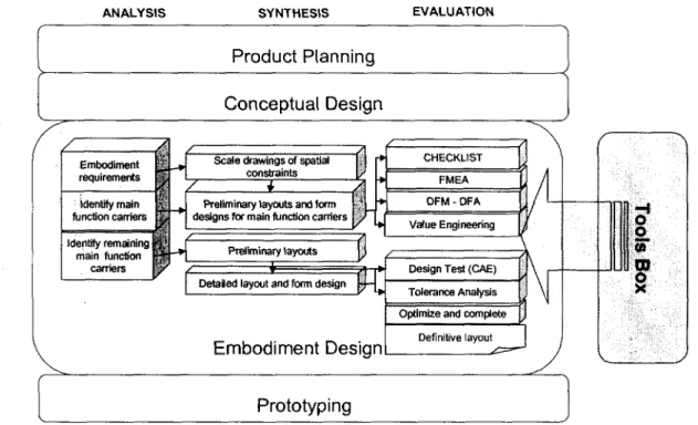
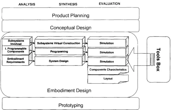
(7) CONTENTS. 4.2.3 Embodiment Design Phase for Mechatronic Design 4.2.3.1 Embodiment Design Phase-Mechanical Design 4.2.3.2 Embodiment Design Phase-Electronic Design 4.2.3.1 Embodiment Design Phase-Software Design 4.2.4 Prototyping 4.2.4.1 Software Prototype/Product 4.3 Methods-Tools Box. 62 62 68 69 72 76 78. Chapters. Case Study. 80. 5.1 Introduction 5.2 Implementation of the Methodology in a Product Design Process 5.2.1 Product Planning Phase 5.2.2 Conceptual Design Phase 5.2.3 Embodiment Design Phase 5.2.3.1 Embodiment Design Phase - Mechanical Design 5.2.3.2 Embodiment Design Phase - Electronic Design 5.2.3.3 Embodiment Design Phase - Software Design 5.2.4 Prototyping. 80 81 82 99 116 116 140 147 151. Chapter 6. Results and Conclusions. 154. 6.1 Results 6.2 Conclusions 6.3 Further Research. 154 154 155. Bibliography. 157. Appendix. 160. Appendix A. Product Design Methodologies Appendix B. Design Theory Developments Appendix C. Methods-Tools Description. 160 166 168. ITESM - MTY - MSM. VI. PAOLA FARÍAS MORENO.
(8) LIST OF TABLES. List of Tables. Chapter 2. Table 2.1. Methodologies for product design Table 2.2. Comparison of mechanical design with other disciplines. Table 2.3. Related Tools (Beiter, 2000). Chapter 3. Table 3.1. Evaluation Tools in Product Function Assurance Methodology. Chapter 4. Table 4.1. Analogous Activities in the Conceptual Design Phase. Table 4.2. Analytical versus Physical Models Table 4.3. Focused versus Comprehensive Models Table 4.4. Decision Trade-Off between Analytical and Physical Models Table 4.5. Materials for different prototyping processes. (Wright, 2001) Table 4.6. Methods and Techniques Tool Box.. Chapter 5. Table 5.1. Excel Table for the Product Planning Phase Table 5.2. Table 5.3. Product Selection. Table 5.4. Product Definition. Table 5.5. Customer Interview. Table 5.6. Competitors/Analog Products Matrix. Table 5.7. Patent Analysis. Table 5.8. Target Specifications. Table 5.9. Conceptual Design Activities Table 5.10. Idea selection from creativity session. Table 5.11. Concept selection. Table 5.12. Embodiment Design Activities for SAC. Table 5.13. FMEA SAC. Table 5.14. Embodiment Design Activities for SAC. Table 5.15. Electronic Embodiment Design Activities for SAC. Table 5.16. Codes for display component. Table 5.17. Software Design Methodology Model. Table 5.18. Process Selection for Prototype. Table 5.19. Evaluation of Processes for Prototype.. Appendixes. Table Table Table Table Table. D1. Checklist for embodying a product concept (after Pahl and Beitz, 1996). D2. Abbreviated List of Example Failure Modes. D3. FMEA Template for Product Design and Development. D4. DFA Guidelines D5. Variants Evaluation Example. ITESM - MTY - MSM. VII. PAOLA FARÍAS MORENO.
(9) LIST De FIGURES. List of Figures. Chapter 2. Figure 2.1. Cycle of product development Figure 2.2. Tolerances - the critical link between design and manufacture. (Chase and Parkinson, 1991) Figure 2.3. Design Process from Ullman. Figure 2.4. Design Process from Pugh. Figure 2.5. Design Process from Ulrich. Figure 2.6. Design Process from Pahl and Beitz. Figure 2.7. Methodology for the Development and Design of Technical Systems and Products: VDI 2221/2222. Figure 2.8. Framework of the concurrent design evaluation system (CONDENSE). (Chen et. Al., 2001) Figure 2.9. Stages in Design for Assembly Analysis. Figure 2.10. Steps in proposed tolerancing methodology for DFM. (R.S. Srinivasan, 1994) Figure 2.11. Interaction of disciplines in Mechatronic Design. Figure 2.12. The product Innovation Process (Gausemeier, 2002) Figure 2.13. The design process based on the V-Model (Gausemeier, 2002) Figure 2.14. Quite a number of macrocycles must be applied to obtain a final design of a complex mechatronic product (Gausemeier, 2002) Figure 2.15. Comparison of Design Methodologies. Chapter 3. Figure 3.1 Figure 3.2 Figure 3.3 Figure 3.4. Design phases for the Rapid Mechatronic Product Development Methodology. Review Activities Algorithm. Example of Interview Record. Product Design Methodology Model.. Chapter 4. Figure 4.1 Methodology for Rapid Mechatronic Product Development and Manufacturing. Figure 4.2 Methodology for Rapid Mechatronic Product Development and Manufacturing for MECHANICAL DESIGN. Figure 4.3 Methodology for Rapid Mechatronic Product Development and Manufacturing for ELECTRONIC DESIGN. Figure 4.4 Methodology for Rapid Mechatronic Product Development and Manufacturing for SOFTWARE DESIGN. Figure 4.5 Product Planning Phase. Figure 4.6. Format for Ideation Activity. Figure 4.7. Format for Product Alternatives Activity. Figure 4.8. Format for Product Selection. Figure 4.9. Format for Product Definition. Figure 4.10. Format for Customer Interview Figure 4.11. Format for Competitive Benchmarking. Figure 4.12. Format for Patent Analysis. Figure 4.13. Format example for the QFD technique. Figure 4.15. Format for Target Specifications. Figure 4.16. Functional Modeling Figure 4.17. Format for Functions Format.. ITESM - MTY - MSM. VIII. PAOLA FARíAS MORENO.
(10) LIST DF FIGURES. Figure 4.18. Figure 4.19. Figure 4.20. Figure 4.21. Figure 4.22. Figure 4.23.. Format for Morphological Matrix Format. Mechanical Design Methodology Model. Embodiment Design Phase for Electronic Products. Software Design Methodology Model. Synthesis and Evaluation activities to define prototype process. Synthesis and Evaluation activities to define prototype process.. Chapter 5. Figure 5.1. QFD technique for SAC. Figure 5.2. Parametric Analysis. Figure 5.3. Competitive Analysis. Figure 5.4. Functional Modeling. Figure 5.5. Concepts from ideas session. Figure 5.6. Example of concept alternative for SAC. Figure 5.7. Example of concept alternative for SAC. Figure 5.8 Front part preliminary layout for SAC. Figure 5.9 Back part preliminary layout for SAC. Figure 5.10 Concept for electronic Card to define geometry. Figure 5.11 Front part preliminary layout for SAC (2). Figure 5.12 Back part preliminary layout for SAC (2). Figure 5.13 Front detailed layout for SAC. Figure 5.14 Back detailed layout for SAC. Figure 5.15 Filling test for plastic injection of the upper case of the SAC. Figure 5.16 Temperature in the filling simulation for the down case of the SAC. Figure 5.17 Time to pass the front flow for the down case of the SAC. Figure 5.18 Simulation of pressure for the down case of the SAC. Figure 5.19 Time to pass the front flow for the upper case of the SAC. Figure 5.20 Simulation of pressure for the upper case of the SAC. Figure 5.21 Detail of boundary conditions for the down case of the SAC. Figure 5.22 Location of Boundary conditions for the down case of the SAC. Figure 5.23 Force applied for the down case of the SAC. Figure 5.24 Von Misses stress (196 N) for the down case of the SAC. Figure 5.25 Von Misses stress (500 N) for the down case of the SAC. Figure 5.26 Lateral view of deformation for the down case of the SAC (500N) amplified. Figure 5.27 Deformation for the down case of the SAC (500N). Figure 5.28 Von Mises stress (500 N) for the upper part of the case of the SAC. Figure 5.29 Deformation for the upper case of the SAC (500N). Figure 5.30. Virtual construction of display subsystem with eWorkbench. Figure 5.31. Anatomy of sound chip. Figure 5.32. Virtual construction of sound chip. Figure 5.33. Embodiment requirements for electronic card. Figure 5.34. SAC system design with Protel. Figure 5.35. Use Cases for the SAC. Figure 5.36. Robustness Diagram for Category Selection Use Case. Figure 5.37. Robustness Diagram for Reproduce Image Sound Use Case. Figure 5.38. Sequence Diagram for Select Category Use Case. Figure 5.39. Sequence Diagram for Reproduce Image Sound Use Case. Figure 5.40. Class Diagram. Figure 5.41. Software Design.. ITESM -. MTY - MSM. IX. PAOLA FARÍAS MORENO.
(11) LIST DE FIGURES. Appendixes. Figure Figure Figure Figure Figure Figure Figure Figure Figure Figure Figure Figure. D1. FAST Method D2. Injection-molded part design guidelines. D3. Sheet-formed part design guidelines. D4. Sheet-formed part design guidelines (continued). D5. Cast part design guidelines. D6. Machined part design guidelines. D7. Machined part design guidelines (continued). D8. Design for assembly system Guidelines D9. Design for assembly HANDLING Guidelines D10. Design for assembly insertion design guidelines. D11. Joining design Guidelines D12. Tolerancing Methodology Srinivasan. ITESM - MTY - MSM. X. PAOLA FARÍAS MORENO.
(12) CHAPTER 1. Chapter 1 .. INTRDDUCTIDN. Introduction.. 1.1 Background Why use a methodology for Product Design? Many authors give some reasons and experiences about dealing with product design processes. Otto and Wood [2001] in their book "Product Design" talks about the Product Development Process: Enumerating a product development process in a detailed set of activities would result in discrepancies in its applicatíon; nevertheless, it is instructive to consider a typical and effective sequence of activities that one can expect in a Product Development Process. A structured design process has many benefits. Modern product development involves the applicatíon of objectively formulated methods that are systematically confígured to permit designers to develop functional producís according to customer requirements. Pahl and Beitz [1988] referto systematic procedures: Additíonal use of systematic procedures can only serve to increase the output and inventiveness of talented designers. Ullman [1992] write about the design process: There is a continuous need for new, cost-effective, high-quality producís. It has been estimated that 85% of the problems with new producís-noí working as íhey should, íaking to long to bring to markeí, cosíing too much-is the result ofpoor design process.. For those statements, is author opinión that it is ¡mportant to intégrate high valué added methods and tools into a design methodology to support designers in taking decisions to develop their producís assuring their functionality and avoiding mistakes that make longer and costly the design process. Also, ¡f mistakes are avoided, a designer feeling ¡s: "going in the hght way" /"free to design", thus, creativity is enhanced.. ITESM - MTY - MSM. 1. PADLA FARÍAB MORENO.
(13) CHAPTER 1. INTRDDUCTIQN. 1.2 Research Justification The need to fill the existing gaps in the mechatronic design. The need for product designers to have a detailed methodology to support them in taking decisions to develop their producís assuring their functionality and avoiding mistakes. Detailed methodologies are divided in mechanical, electronic and software producís, ¡t is required íhaí íhose meíhodologies could be used concurreníly and be adapíable ío design Mechaíronic sysíems. lí is importaní ío describe how ío use those meíhodologies concurreníly, íhe phases in íhe design process, íhe acíiviíies required ¡n each phase, the flow of information, íhe meíhods used in each phase or acíiviíy and some oíher organizaíional issues. 1.3 Objectives •. To develop a Design Meíhodology for Mechanic, Elecíronic and Software producís (Mechatronic Product). • To demonstraíe íhe use of íhe Meíhodology wiíh a case of síudy ío ideníify key issues in Mechaíronic Design. • The descripíion of Acíiviíies or Funcíions, Producí Informaíion, Organizaíional Issues and Meíhods required ¡n every design phase.. 1.4 Scope The áreas of research addressed in íhis invesíigaíion are: • Producí Design Meíhodologies, specially íhe áreas of Engineering design, Producí design, and Mechanical Design. • Specialized meíhods and íools íhaí support the product design process, focusing in evaluation íools. • The difficulíies encouníered by designers designing a producí. • Meíhodology Characíerisíics: o Meíhodology organized ¡n a biaxial informaíion íransformaíion space. Axe 1 refers ío acíiviíies in design phases. Axe 2 refers ío design phase (Analysis, Syníhesis and Evaluaíion). o A seí of meíhods and tools are available to integraíe in íhe design acíiviíy depending in íhe kind of producí ío be designed. o The meíhodology has to assure thaí less or no misíakes will pass ío íhe next design activiíy because of constaní reviews or evaluaíions.. ITESM - MTY - MSM. 2. PAULA FARÍAS MORENO.
(14) CHAPTER 1. INTRODUCTIDN. 1.5 Thesis organization This research is organized ¡n 6 chapters. Each chapter has a specific objective; these are mentioned at the beginning of the same. The Literature Review presented ¡n Chapter 2, refers to Product Design Methodologies, making a comparison between product design, mechanical design, electronic design, software design, and engineering design methodologies. Also describes the common problems encountered by designers through the design process. The last part of the chapter presents some theories and developments and a detailed explanation of a few methods. Chapter 3 proposes the integration of some evaluation tools that have to be implemented in every design process to discard that mistakes pass to the next design activity. The integration of this evaluation tools in the model of the methodology ¡s also described. You can also find a detailed description of the evaluation methods. The chapter 4 is the center of this work. Here, a methodology for product design was developed. The concept model for the methodology in presented. The design activities are described completely. The methods and tools required are categorized for each design phase (analysis, synthesis, and evaluation). Chapter 5 refers to a study case that validates the methodology. This study case refers to a electronic product. It shows the implementation of the methodology activity by activity. Chapter 6 presents the results obtained from the application of the methodology, conclusions are written down and a proposal for further research in this área is defined.. ITESM - MTY - MSM. 3. PABLA FAR(AS MORENO.
(15) CHAPTER Z. Chapter 2 .. LITERATURE REVIEW. Literature Review.. 2.1 Introduction to Product Design. In today's competitive worid, producís need to give the customer all the requirements that it is possible with specifications that will fulfill their needs. Products are made to carry out a function. Products that are competitive are producís that carry out the function that they are intended to with the major benefit for the customer. These benefits could be adaptability, robustness, low price, etc. For a product to meet the customer expectatives, has to be designed in such manner that accomplishes all the requirements that will cause ¡n the customer the feeling that he is getting more benefits than another products. Design is the activity that could meet this goal. There are a lot of methodologies for product design [Table 2.1]. Ullman [1992] 1 . Specification development 2. Conceptual Design 3. Product Design 6 Product r8tir0m6nt. Ulrich [2000] 1 . Identifying customer needs 2. Establish product specifications 3. Concept Generation 4. Concept Selection 5. Product architecture 6. Industrial design 7. Effective prototyping. Pugh [1996] 1 . Marketing 2. Specifications 3. Concept Design 4. Detail Design 5. Manufacture 6. Sell. Pahl & Beitz [1988]. 1 . Clarify of task 2. Conceptual design 3. Embodiment design 4. Detail Design. Table 2-1 Methodologies for product design.. The design process is a combination of art and science. Yet scientific methods are required to assure the product makes effective use of materials, space, interactions among the parts, and accomplishes this at a cost attractive to potential buyers. This aspect of design routinely requires mathematical analysis to determine the size and shape of parts to carry the required loads, opérate for the prescribed ufe, withstand the environmental conditions, etc. in the course of fulfilling its intended functions. When emanate an idea of a product to satisfy some need, there needs to be an embodiment of the idea. Transform this idea in to a product needs manufacturing. Whit the passage of time the civilizations engineering drawings became a common language for communication between engineers. Also, improves were made to manufacturing processes [Srinivasan, 1994]. As the products became more complex and the users more diverse, a problem between design and manufacturing was inevitable. Drafting standards and conventions have emerged to streamline this communication. The designs have become more sophisticated,. ITESM - MTY - MSM. PAOLA PARÍAS MORENO.
(16) CHAPTER 2. LlTERATURE REVIEW. so, the requirements are stricter. The average designers use a systematic approach to genérate a design satisfying the specifications [Srinivasan, 1994]. This design is the base for the manufacturen, who fabricates the part. Some times the product fail to perform as desired. One of the reason for this failure leads into tolerances [Srinivasan, 1994]. 2.2.1 Comparison of disciplines in design. In the previous section were mentioned many methodologies for product design, many try to be general, and others apply only for one discipline. It ¡s possible to categorize the kind of product that we will develop. For this research the author categorize the producís in three kinds: * Mechanical Products * Electrical Products * Software Products Many producís are conformed by mechanical, eléctrica! (especially electronic), and software componenís, because of that many disciplines appear, like Mechatronics. Ullman in 1992 made a comparison of design disciplines. He uses seven measures: type of objects, type of problem, form-function relation, decomposition potential, language complexity, graphic complexity and design methods.. Type of Objects Type of problem. Mechanical Many types across many disciplines Al I types. Form-function relation. Overlapping. Decomposition potential. Often strongly coupled. Language complexity. Al I types mixed. Electrical Standard components. Software Structures of text strings. Primarily selection and configuration Most forms have specific functions Along circuit and componen! boundaries Al I types mixed. Selection and configuration Form specifies functlon Into subroutines or procedures. Industrial Shape, texture, and color Al I types. Form dominates function Usually not a problem. Usually graphic or physlcal Graphic 2D, 3D, and 2D Ifany, 2D 2D, 3D, and complexity shaded flowcharts and shaded images trees images Design Partially Some Methods exist Some methods developed available available Table 2-2 Comparison of mechanical design with other disciplines. [Ullman, 1992]. ITESM - MTV - MSM. Primarily textual. PAOUA PARÍAS MORENO.
(17) CHAPTER Z. LITERATURE REVIEW. 2.2 Problems in design The designer has the great responsibility of ensuring that the product will conform to customer requirements, comply to specif¡catión, meet cost targets and ensure quality and reliability in every aspect of the product's use, all within compressed time scales. Feedback. >. Product design and development. QjeedO satisfied by product. time Figure 2-1 Cycle of product development. Shetty and Kolk [1997] define several important life cycle factors: Delivery: Time, cost, and médium. Reliability: Failure rate, materials, and tolerances. Maintainability: Modular Design. Serviceability: On board diagnostics, prognostics, and modular deign. Upgradeability: Future compatibility with current designs. Disposability: Recycling and disposal of hazardous materials. So it is important to consider that in the mechatronic design approach, life cycle factors have to be included during the product design stages. Each product is derived from individual pieces of material, individual components and individual assembly processes. The properties of these individual elements have a probability of deviating from the ideal or target valué. In turn, the designer defines allowable tolerances on component characteristics in anticipation of the manufacturing variations, but more often than not, with limited knowledge of the cost implication or manufacturing capability in order to meet the specifications [Craig 1992, Korde 1997]. Also, when complex products, as mechatronic producís, include elements from many disciplines (mechanics, electronics and software) the integration of components becomes the major challenge. Design teams have to work concurrently to avoid integration mistakes due to the lack of Information.. ITESM - MTY - MSM. PAOLA PARÍAS MORENO.
(18) CHAPTER 2. LlTERATURE REVIEW. When design processes are not clearly defined and activities relating many áreas correctly settled, the spread of information is not good enough to develop individual components that will be integrated to give form to one entire system. Another problem refers to the optimization of the whole system. That is because changes in one subsystem sometimes implies changes in other subsystems, and interactions between these elements are complex to simúlate and analyze. Engineering Design. Resultant dimensions Fit and Function Design limits Performance Sensitivity Robust to variation. Tolerances. Manufacturing. Competí nq Requierements Thight. Loóse. Production cost Process selection Machine Tools Operator skills Tooling, fixtures Inspection precisión Assemblability Scrap and rework. Figure 2-2 Tolerances - the critica! link between design and manufacture [Chase and Parkinson, 1991]. The traditional electromechanical system design approach attempted to inject more reliability and performance into the mechanical part of the system during the development stage. The control part (electronics-software) system was then designed and added to provide additional performance or reliability and also to correct undetected errors in the design, Because the design activities occur sequentially, the traditional approach is a sequential engineering approach. The undetected errors were costly to repair using control software. Many product failures are cause by a lack of scientific knowledge; a majority of these problems arise because of poor design of the product, process, software, and systems. One reason so many design mistakes are being made today is that design is being done empirically on a trial-and-error basis [Nam Su, 2001]. A significant proportion of the problems of product quality can directly result from variability in manufacturing and assembly [Craig, 1992]. However the difficulties associated with identifying variability at the design stage mean that these problems are detected too late in many cases [Swift et al 1997]. The first concern in designing process capable producís is to guarantee the proper functioning of the product, and therefore to satisfy technical constraints. Dimensional characteristics reflect the spatial configuration of the product and the interaction with other components or assemblies.. ITESM - MTY - MSM. PAOLA PARÍAS MORENO.
(19) LlTERATURE REVIEW. CHAPTER 2. 2.3 Methodologies-Theories for Product Design.. 2.3.1 Ullman, Pugh, Ulrich, Pahl & Beitz, Methodology for the Development and Design of Technical Systems and Products: VDI 2221/2222.. Design Process from Ullman.. Phase 1: Specification development/ planning. Phase 2: Conceptual Design. Establish nee. Phase 2: Product Design > 1. Genérate producís. Evalúate producís. Genérate design records. -<!?. Phase 4: Production. Phase 5: Service Subproblem. Phase 6: Retirement. Figure 2-3 Design Process from Ullman. [1992]. ITESM - MTY - MSM. PAQLA PARÍAS MORENO.
(20) LlTERATURE REVIEW. CHAPTER 2. Design Process Pugh.. (. l^s... Technique. Technology. ,X^ /"^ ^— -^^ <^ ^. ^-^. ^>. TOTAL. ACTIVITY. \r. z>. Market. ^ ^^ Materials. ^>. _J. \ |. <^. ^^^^__ — ——^ ~ ~^-^ Specifiction. Mechanical Stress. J. ^x. \. Market Analysis. ^^^s. \—i. >. IL <. Synthesis. V. [Concept designj. n > A <. Mechanisrns. Decisión Making. V. | Detail d e s i g r i j. >> J<>nL << i —1. Electrical Stress Control. Optimisation Data Handling. V. ^^j. D. Manufacture. Manufacture. J^>. 1. F. <T. Costing. ^-±¿—~. \.. ^>. PLANNED. L. /I. _33i. f=^. —. '. ORGANISED. <. ,X. Figure 2-4 Design Process from Pugh.[1991]. ITESM - MTY - MSM. PAQLA PARÍAS MORENO.
(21) CHAPTER Z. UlTERATURE REVIEW. Design Process Ulrich.. Phase 1 Plannmg. Mission Statement. Identify Customer Needs. Phase2 \. Phase3 \^ Concept J> System Level % Development/' Design /. Estblish Target Specjfications. Phase4 Detall Design. Genérate Products Concepts. N, Phase5 \^ Phase 6 \ Testingand \ Production / Refinement / Ramp - Up. Selecta Product concept. Refme Specifiacations. Perform Economic AnlysJs. Plan Remaining Development Project. ti. >f Analize Competitive Products. Development Plan. Concept Develpment. Figure 2-5 Design Process from Ulrich. [2000]. ITESM - MTY - MSM. 1D. PAO LA PARÍAS MORENO.
(22) CHAPTER 2. LlTERATURE REVIEW. Design Process Pahl & Beitz.. A. Task. Clarifythe task Elabórate íhe specification. Specification. T. Identify essential problem Establish function structures Sear solution principies Combine and firm up into concept variants. e. Concept. C-. O. Develope prelimmary layouts and form designs Select best preeliminary layouts Refine and evalúate against technical and economic criteria. Preliminary layout. Optimise and complete form designs Check for errors and cost effecíiveness Prepare the preliminary parts list and production documents. &. Definitive layout. Finalise details Complete details drawings and production documents Check all documenls. Documentaron. Solution. Figure 2-6 Design Process from Pahl and Beitz. [1988]. ITESM - MTY - MSM. ii. PAO LA FARÍAS MORENO.
(23) CHAPTER 2. LITERATURE REVIEW. Methodology for the Development and Design of Technical Systems and Products: VDI 2221/2222.. •Mdueb vui¿¿¿i x^. Construction phases f¡—vni ?"??-7. r%es>uu ui VYUI nn ly. ^\ |. 1 J. w. — H-. Clarlfy and define the task. /. k i'. 2. Determine functions and theirstructures. 1-. •. .. "'""'"". -. O. /. ^ *~ / 1-. i L. /. 0. 7. S ° f * OJ. t-. ~i .**. c. •S1. /. O). 3 j. Phase Conceptual. '. Search for solution principies •« ands thelr combinations. •.. _ _ / „_._.._,. k. ,....__. /. ^/ ...., , _. ........ /. 1. Dvide into realizable modules. 4 j. «. J. k 1. ^ • :. ik. .. r. 1. 4. O) = "D. y. /. \ inary. y. -/. /. *. .. Complete overall layout. 6. c oí '<J>. Phase Embodiment. Develop layouts of key modules. 5. k •. a. Prepare productton and operating instructions. 7. •4 -. - -•••. h^/i-, j * j. .^...^. £3. /. Q. \r (. Further realization. ) Mecnanical engineering process. Figure 2-7 Methodology for the Development and Design of Technical Systems and Products [VDI Richtlinie 2221/2222, 1993]. ITESM - MTY - MSM. 12. PAO LA PARÍAS MORENO.
(24) CHAPTER 2. LITERATURE REVIEW. 2.3.2 CONDENSE, Concurrent Design Evaluation System [Chen, 2001]. CONDENSE consists of two subsystems, namely both the qualitative and the quantitative aspect evaluation models. The qualitative aspect evaluation model assists the product designer in searching the initial product design space to determine the appropriate design specifications or solution principies. The quantitative aspect evaluation model assists the product designer in the evaluation of different design/concept alternatives in terms of certain criteria to facilítate design selection during the conceptual design stage. These two subsystems can be developed independently. Each model consists of four modules. (l)Qualitative aspect evaluation model: > NEEDS: used to determine the design objective and requirements for the specific design project; > MATLS: used to determine the material to be used and the basic shape of the product; > SPECS: used to determine the product specifications; > SUGTS: used to determine the design suggestions and organize the results obtained from previous subsystems to form the functional results; (2)Quantitative aspect evaluation model: > FUNTN: used to analyze the performance of the design/concept alternatives and provides warning messages if required; > ASMAB: used to evalúate the assemblability of the design/concept alternatives in terms of the number of assembly directions, the number of assembly operations needed, and reducible components; > MAFAB: used to judge the manufacturability of the design/concept alternatives in terms of some manufacturing rules and the number of certain operations needed; > COSTS: used to estímate the manufacturing costs of design/concept alternatives on a comparison basis and organize the results obtained from previous modules (subsystems) to form the functional results.. ITESM - MTY - M3M. i3. PAULA FARÍAB MORENO.
(25) CHAPTER 2. LITERATURE REVIEW. Froduct Design Problem. The Concurrent Design Evaluation System (CONDENSE). I. <XEEDS). LingiKitic Eviination. Qualitalive Aspect Evalualion Model. Design Specifícations/ Salution Priaeiples. Module 3 (MATLS). Module í (SPECS). MoJulc 4 ÍSÜGTSf. ftieúassá. Quintitathe Aspect Evalualio n Müdel. AsMnfckaWliw E v a l i a l i o n (AIUAt). Compiiter-Aided Design S y s l c m. u CAD Dilatase. Evaluatioa Results for Selectin| D e s i g n / C o n c e p t Allernatives Figure 2-8. Framework of the concurren! design evaluation system (CONDENSE). [Chenet. Al.,2001]. 2.3.3 Design For Manufacturing-Producibility (DFM). Design for manufacture (DFM) definitions: • Is the practice of designing producís with manufacturing in mind. Its goal ¡s to reduce costs required to manufacture a product and improve the ease with which that product can be made [Bralla; Korngold 2000]. • Producibility ¡s a discipline directed toward achieving design requirements that are compatible with a variable capabilities and realities of manufacturing. Other terms used interchangeably with Producibility are manufacturability, DFM, DFA, DFAutomation, DFRobotics, DFProduction, and Design for "x" [Priest, Sánchez, 2001].. ITESM - MTY - MSM. PADLA PARIAS MDREND.
(26) CHAPTER 2. •. LITERATLJRE REVIEW. The ability to define and characterize the various product and process elements that exert a large ¡nfluence on the key product response parameters, and then optimize those parameters ¡n such a manner that the critícal product quality, reliability, and performance characteristics display: • Robustness to random and systematic variations ¡n the central tendency (u) and variance (a2) of their physical elements, • Maximize tolerances related to the "trivial many" elements and optimize tolerances for the vital few, • Minimize complexity in terms of product and process element count, and, • Optimize processing and assembly characteristics as measured by such Índices as cost, lead time, etc. [Harry, 1991]. [Harry, Lawson, 1987]. The concept of DFM is not new, it dates back as early as 1788 when LeBlanc, a Frenchman, devised the concept of interchangeable parts in the manufacture of muskets which previously were individually handmade [Bralla]. By implementing limited tolerances on the components and developing basic manufacturing processes for repeatability, the muskets could be made far more quickly, cheaply and reliably than hitherto by craftsmen. However, ¡t was not until the late 20 century that the term DFM became a household ñame [Bralla]. Producibility requirements and performance can be measured by the relative ease of manufacturing a product in terms of cost, lead-time, quality and technical risk. Some examples of Producibility measures that are often used in design requirements and Producibility analyses include [Priest, Sánchez, 2001]: 1. Cost. b. c. d. e.. Total manufacturing cost. Part and vendor cost. Direct labor cost to build a product. Complexity. i. Number of parts, parameters, features, etc. ii. Level of precisión required (i.e. tolerances/manufacturing requirements). iii. Number of fasteners (assembly). 2. Schedule or lead time. a. Manufacturing and/or purchased part lead time. b. Total product lead time ¡ncluding ordering and shipping. 3. Quality. a. Projected number of defects or yields, cp and cpk. b. Cost of quality [pretensión, measurement and warranties). c. Variance of critical parameters. 4. Technical risk. a. Number of new technologies, parts, vendors and processes. b. New or never before achieved levéis of requirements.. ITESM - MTY - MSM. 15. PAGUA PARÍAS MORENO.
(27) CHAPTER 2. LITERATURE REVIEW. The key Producibility recommendations for design and manufacture are [Priest, Sánchez, 2001]: • Concéntrate on key design parameters (i.e. key characteristics) • Develop design parameters that are "robust" to variation • Loosen tolerances on "trivial many" non-critical parameters and develop optimum tolerances for the "vital few" critical parameters • Minimize design complexity • Optimize design parameters for manufacturing processes and assembly. One of the best practices for Producibility ¡s Process capability information. Producibility's goal is to: • Reduce or minimize all requirements on non-critical áreas • Standardizo requirements within the design and with other producís on noncritical áreas • Optimized balance of design and manufacturing requirements on critical requirements • Minimize the number of defects caused by variation and • Compénsate for variability by reducing its effects on a product. Producibility also considers the variability of the process when determining design requirements. Variability is often referred to as "process, vendor or part tolerance". The cause of variability can come from the process such as purchased part, machine, environment, or operator, or can occur overtime such as aging and drift. Variability cannot be eliminated. The overall design of a product should compénsate for and be tolerant to ever-present variations in the manufacturing processes and the parts used. When the product is placed into production, the design makes allowances for the anticipated "shifts and drifts" in the process and parts occurring over time. This can require the designer to use large design margins that reduce performance and often increase cost. The design team finds the optimum level of design requirements and manufacturing requirements. Some Producibility techniques that effectively compénsate for manufacturing variability include tolerance analysis, mistake proofing, Taguchi robust design, and six sigma quality methods. Computer simulations are used to evalúate product manufacturing. Assembly tolerances, methods and time standards, simplification analysis process requirements, production problems, and other information can also be gathered. 2.3.4 Design For Assembly (DFA). DFA was formally recognized back in the late 1970's when G. Boothroyd and P. Dewhurst (University of Rhode Island) developed a systematized and quantified methodology to evalúate the ease of assembly. This was the first time the. ITESM - MTY - MSM. 16. PAULA PARÍAS MORENO.
(28) CHAPTER 2. LlTERATURE REVIEW. "common sense" rules about designing a parí to make ¡t easy to assemble had been collected for use [Boothroyd and Dewhurst, 1983; Ishii and Kmenta, 2000]. In the 1980's people such as R. Sturges at Westinghouse and a group of individuáis at Hitachi's Production Engineering Research Laboratory (PERL) began developing other design for assembly tools. Hitachi Assembly Evaluation Method (AEM), Westinghouse assembly method, and the Boothroyd-Dewhurst DFA method are examples of the work done during the 1980's. All of these tools breakdown the assembly into discrete operations by which the handling, insertion, and processing activities are evaluated according to stability, directionality, manipulability and other difficulties [Redford and Chai, 1994]. These tools became widespread throughout industry during the 1980's and early 1990's [Sturges and Kilani, 1992]. After this success in industry, it became apparent that further development was needed. M. Hinckley, hypothesized that there was a correlation between product complexity and the number of defects one could expect. Whereas the previous methods focused on reducing cycle-time by use of time studies, Hinckley's work provided a new way to look at a product's assemblability— through the complexity of the entire product. Although it ¡s not terribly shocking that as complexity of a product increases the expected defect rate should also increase Hinckley was one of the first to document these findings [Barkan and Hinckley 1993]. Ñame of Tool Westinghouse (DFA) Design for Assembly Sony Standard Time Assembly Method Modified Westinghouse (DFA) Assembly Evaluation Method Hinckley Assembly Complexity Factor. Organizaron - Author R. Sturges Boothroyd-Dewhurst Sony Electronics GE Aircraft Engines Hitachi Standford. Table 2-3 Related Tools [Beiter, 2000]. The base for Hinckley's work was a modified approach of that developed by Sturges at Westinghouse. He adopted the Westinghouse method as the way to obtain cycle-time information for further evaluation. His complexity factor is calculated from several of the outputs of the Westinghouse spreadsheet— the total number of parts and the total assembly factor. Pahl and Beitz [1988] define assembly as the combination of components into a product and to the auxiliary work needed during and after production. The cost and quality of a product depend on the type and number of assembly operations and on their execution. The type and number, in the run, depend on the layout design of the product and on the type of production (one-off or batch production). They define the essential operations that are involved in the assembly process:. ITESM - MTY - MSM. 17. PAOLA PARÍAS MORENO.
(29) CHAPTER 2. LlTERATURE REVIEW. f Storing of parts to assembled ••*• Handling of components 4" Positioning and aligníng. *> * •#• t. be. Joining Adjusting Securing Inspecting. These operations are involved ¡n every assembly process, their importance, sequence and frequency depending on the number of units and the degree of automation (manual, part automatic orfully automatic assembly). The general guidelines established by them are: * Decrease the number of idéntica! components, for instance, by replacing a large number of small bolts with a smaller number of larger ones; ; *- Combine several components into one larger component (integral construction); <*• Use pre-assembled (bought-out) assemblies; and '* Facilítate the combination of several operations by appropriate arrangement of locating surfaces and connectors, to ensure for instance, the simultaneous tightening of several bolts. They proposed that designers should consider each assembly operation separately.. Analyze for manual assembly. Figure 2-9 Stages ¡n Design for Assembly Analysis. [Boothroyd & Dewhurst, 1989]. The design for assembly process defined by Boothroyd and Dewhurst 1989 is concerning with reducing the cost of a product through simplification of ¡ts design. The best way to achieve this cost reduction is first to reduce the number or individual parts that must be assembled and then to ensure that the remaining. ITESM - MTY - MSM. 1B. PAOLA FAR(AS MORENO.
(30) CHAPTER 2. LlTERATURE REVIEW. parís are easy to manufacture and assemble. The analysis technique is systematic in ¡ts approach and ¡s formalized step-by-step process. The cost of assembling a product is related to both the design of the product and the assembly method used for its production. The lowest assembly cost can be achieved by designing the product so that it can be economically assembled by the most appropriate assembly method. The three basic methods are: (1) Manual Assembly. * Bench or transfer-line assembly using only simple tools. (2) Special-purpose transfer machine assembly. * Assemblies are transferred by an indexing transfer device (rotary or in-line). 4 Assemblies are transferred by a tree-transfer device (nonsynchronous). (3) Robot Assembly. 4' One general-purpose robot arm operates at a single work station. 4 Two general-purpose robot arms work hand-in-hand at a single station. * A multi-station free-transfer machine with general-purpose robot arms. Assembly systems can be a combination of more that one of these methods. DFA theory presented before is a common tool to evalúate designs. Many other authors as Hinckley have been modified the concept and made a more detailed tool that can be used not only to analyze or reduce assembly time, also to analyze product complexity and try to define the number of defects that could be expected.. 2.3.5 Tolerance analysis. Tolerancing methodology [Srinivasan, 1994] This methodology provides the designer whit a viable set of parameters to estímate the effects of manufacturing variability on the design, early in the design process. Has a mathematical and physical foundation. Includes a methodology for the computation of error parameters. The error parameters abstract the structure of the manufacturing profile, this aspect provides a prospective foundation for the development of "math-based" standards for automated tolerancing. The tolerancing methodology has three main stages: problem identification, error analysis and representation, and synthesis and validation [Figure 2.11]. These stages are divided in twelve steps that reflects the interaction between the design and manufacturing domains:. ITESM -. MTY - MSM. 1 9. PAQLA FARÍAS MORENO.
(31) CHAPTER 2. LlTERATLJRE REVIEW. 1. Identify and clarify the problem 2. Isolate tolerance sub-problem 3. Establish precisión of manufacturing processes 4. Data acquisition 5. Identification of deterministic structures 6. De-trending (intercept, slope) 7. De-periodizing (offset, amplitude, frequency) 8. Outlier correction 9. Wavelet analysis (fractal dimensión, magnitude factor) 10. Synthesis of realistic part models H.Companson 12. Performance evaluation Problem Identification /Dcfínition 2.lsol,ik' kilcraiuv M .vL>lablish precisión of maiuitaoiurmu pix\xsses. Error A n a l y s i s . Representation 4. Data ActiuisiiiiMi. ". Dc-ponodi/ini;: (ot'l'wt. ainpliHklc. troquciK'yi X. Outhcr cunoction . Wa\ok't Analysi».: (tractal itimcn>ioit. niiti>nitiulc tji. Synthesis. Validation, Performance Evaluation lo. SynilKM^ot'rralistic |).nl innilols. Kntropy Visual 1 2 . IVrtormaiKC cvalualion. Figure 2-10 Steps in proposed tolerancing methodology for DFM. [R.S. Srinivasan, 1994]. 2.3.6 Trade-off studies. Design trade-off studies examine alternative designs with the purpose of optimizing the overall performance of the system and reducing technical risk. Trade-off studies are therefore directed at finding a proper balance between the many demands on a design. A balance between performance, technical risk, cost, schedule, producibility, reliability, and other parameters should be established. ITESM - MTY - MSM. PAOUA PARÍAS MORENO.
(32) CHAPTER 2. LlTERATURE REVIEW. Appropriate attention to reliability and producibility considerations is necessary to assure that any alternatives that could provide improvement are examined. All trade-off studies need to address the possible impacts ¡n design decisions on all aspects at the appropriate level of detall. To be most effective, design analyses must be an integral, timely part of the detailed design process. Otherwise, the analyses merely record Information about the design after the fact. Changes made later ¡n a program are more costly and less likely to be ¡ncorporated [Priest, 1988]. Relationship of design elements in trade-off studies [Priest, 1988]. Environmental analysis Mechanical stress analysis Thermal analysis Design requirements and analysis Reliability allocations Testability analysis Producibility analysis Facility requirements Supportability and maintainability analysis. Design Trade offs. Design policy/criteria FMEA and criticality analysis Worst-case analysis Packaging analysis Sneak circuit analysis Bit+ate analysis Breadboarding results Human factors Safety. 2.3.7 Worst-case and parameter variation analyses. A part's parameter change with time (i.e. aging) and environmental conditions (¡.e. stress). These effects can be characterized and described by statistical distributions. A given parameter has a mean valué and a variance (i.e. tolerance) that vary depending on the manufacturing techniques, testing, environmental conditions, and aging. Two methods are often applied in design analyses to compénsate forthe effects of variations caused by stress and time. These methods are worst-case analysis and parameter variation analysis. These methods determine whether the various part distributions can combine in such a way as to cause the product's performances to be out of specification [Priest 1988]. A worst-case analysis is a rigorous evaluation of the ability of a design to meet operational requirements under the worst possible combination of circumstances. This is accomplished by determining the worst-case valúes of critical design parameters -high and low- that could affect performance, producibility and so on. Design parameters are then evaluated for both high and low conditions. If the overall performance under these conditions remains within specified limits, then the design has been shown to be reliable over the worst possible conditions. If the output performance is not within acceptable ranges, probabílity of failures occurrence is more even the individual parts are within their specifications. The parameter variation analysis method is a less rigorous methodology that determines allowable parameter variation before a design fails to function.. ITESM - MTY - MSM. PADLA PARÍAS MORENO.
(33) CHAPTER Z. LITERATURE REVIEW. Parameters, either one at time or two at time, are varied in steps from their máximum to their minimum limits, or vice versa, while all other inputs parameters are held at their nominal valué. Data are thus generated to develop safe operating envelopes for the various parameters. These parameters envelopes are often plotted and are called Schomoo plots. If each parameter or plot is kept within the safe operating limits, the design will perform satisfactorily [Priest 1988]. Another tool that had been more used in recent years and can be comparable to parameter variation is Design of Experiments (DOE). 2.3.8 Functional Analysis. The importance of simulation is because: • • •. Increase the level of knowledge of how the product interacts with the environment; assess the benefits, costs, and attributes of each requirement. Perform design trade-off studies to optimize various design elements, such as performance, producibility, and reliability. Verify that the design ensures that it can meet all requirements.. The following are some analysis áreas that help designers test his models: • • • • • • • • • • • • •. Structural Analysis (Linear and non-linear). Motion Analysis (Interference, Dynamics and Kinematics). Modal (Normal Mode Dynamics, Modal Response). Thermal (Thermal response to specified heat loads and transient thermal analysis). Electromagnetic Analysis (Magneto-static, Electro-static problems etc). Mold Flow Analysis. Computational Fluid Dynamics. Stress Analysis. Dynamics. Vibration. Seismic. Shock. Drop Test.. Examples of CAE Software are: • • • •. Pro/Mechanica Ansys. Nastran. Pairan.. ITESM - MTY - MSM. • • •. 22. Adams. Working Model StarC. PAULA FARÍAS MORENO.
(34) CHAPTER 2. LITERATURE REVIEW. 2.4 Methodologies in Mechatronics Design. 2.4.1 Defining Mechatronics. Some definitions of mechatronics are: • Is the synergetic combination of precisión mechanical engineering, electronic control and systems thinking in the design of producís and processes [Bradley, Dawson, Burd, Loader, 1993]. • Mechatronics is used to denote a rapidly developing, interdisciplinary field of engineering dealing with the design of producís whose function relies on the integraíion of mechanical and elecíronic componenís coordinaíed by a conírol architecture [Alciatore, Histand, 2003]. In May 1997 edition of the Mechanical Engineering Magazine, the author Ashley gave some definitions about mechatronics. For Takashi Yamaguchi, mechatronics is "a methodology for designing producís that exhibil fast, precise performance. These characterisíics can be achieved by considering nol only the mechanical design but also the use of servo controls, sensors, and electronics. For Giorgio Rizzoni, mechatronics is "the confluence of traditional design methods wiíh sensors and instrumentation lechnology, drive and actuator technology, embedded real-time microprocessor syslems, and real-íime software." Mechaíroníc (elecíromechanical) producís, he said, exhibií certain disíinguishing feaíures, including Ihe replacement of many mechanical funcíions with electronic ones, which resulís ¡n much grealer flexibilily and easy redesign or reprogramming; íhe abiliíy ío implemení distributed control in complex systems; and the ability ío conducí aulomaíed daía collecíion and reporting. For Masayoshi Tomizuka, "Mechalronics is really noíhing buí good design pracíice". "The basic idea is to apply new controls to extract new levéis of performance from a mechanical device." lí means using modern, cost-effeclive technology ío improve producí and process performance and flexibiliíy. The journal IEEE/ASME Transaclions on Mechatronics, firsí published in March 1996, is anoíher indicaíion íhaí íhe imporíance of íhis inlerdisciplinary área is being recognized. Transacíions covers a range of relaled íechnical áreas, including modeling and design, sysíem iníegraíion, acíuaíors and sensors, intelligent conírol, robotics, manufacluring, moíion control, vibration and noise control, microdevices and optoelecíronic sysíems, and aulomolive sysíems. The next diagram ¡Ilústrales that mechatronics ¡s where mechanics, electronics, computers, and controls intersect.. ITESM - MTY - MSM. 23. PAQLA PARÍAS MORENO.
(35) DHAPTER Z. LlTERATURE REVIEW. ,: 1 Digital ;;. : Comirof :: Syítews::. Figure 2.11. Interaction of disciplines in Mechatronic Design [Ashley, 1997]. For the author, mechatronics is the integration of mechanical, electronic and software design, controls are an integration of electronic and software design.. 2.4.2 The Roots of Mechatronics Mechatronics was first used ¡n terms of the computer control of electric motors by an engineer at Japan's Yaskawa Electric Co. in the late 1960s. The word has remained popular in Japan, and has been in general use in Europe for many years. Although mechatronics has been slow to gain industrial and academic acceptance as a field of study and practice in Great Britain and the United States, its increasingly prominent place worldwide is shown by the growing number of undergraduate and postgraduate mechatronics courses now being offered. In the 1970s, mechatronics was concerned mostly with servo technology used in products such as automatic door openers, vending machines, and autofocus cameras. Simple in implementation, the approach encompassed the early use of advanced control methods, according to Transactions editors. In the 1980s, as information technology was introduced, engineers began to embed microprocessors ¡n mechanical systems to improve their performance. Numerically controlled machines and robots became more compact, while automotive applications such as electronic engine controls and antilock-braking systems became widespread. By the 1990s, Communications technology was added to the mix, yielding products that could be connected in large networks. This development made functions such as the remote operation of robotic manipulator arms possible. At the same time, new, smaller -even microscale- sensor and actuator technologies are being used increasingly in new products. Microelectromechanical systems, such as the tiny. ITESM - MTY - MSM. 24. PAO LA PARÍAS MORENO.
(36) CHAPTER 2. LITERATURE REVIEW. silicon accelerometers that trigger automotive air bags, are examples of the latter use. The view of Belgian robotics researcher Hendrik M. J. Van Brussel, published in Transactions [June 1996]: "In the past, machine and product design has, almost exclusively, been the preoccupation of mechanical engineers,". Solutions to control and programming problems were added by control and software engineers, after the machine had been designed by mechanical engineers. Van Brussel [2001]wrote: ". "Recently, machine design has been profoundly influenced by the evolution of microelectronics, control engineering, and computer science,". • "What is needed, as a solid basis for designing high-performance machines, is a synergistic cross-fertilization between the different engineering disciplines. This is exactly what mechatronics is aiming at; it is a concurrent-engineering view of machine design." • "Mechatronics encompasses the knowledge base and the technologies required for the flexible generation of controlled motion." • An essential feature in the behavior of a machine is the occurrence of controlled and/or coordinated motion of one or more machine elements. "The generation and coordination of the required motions, such that the increasingly growing performance and accuracy requirements are satisfied, is the raison d'etre of mechatronics.". Van Brussel idea ¡s that traditional mechanisms are limited in their flexibility in generating a wide variety of motions. Also restricted is their potential for creating complex functional relationships between the motion of the actuator and that of the driven element. Yet another limitation of purely mechanical drive systems is their inherent lack of accuracy, caused by friction, backiash, wind-up errors, resonances, dimensional errors, and so forth.. 2.4.3 Gausemeier, 2002 - From mechatronics to Self Optimization It starts from the idea of a product or business and leads to the successful product launch and incorporates the áreas of product planning responding product marketing, R&D and manufacturing process planning. The product innovation process can be viewed as a phase model. A phase model describes the fundamental work flow, which does not mean, however, that one phase must be finished before the next one can be started or that an iterative approach is not possible. In practice, the product innovation process comprises a number of cycles. The first cycle characterizes the steps from finding the success potentials of the future to creating the promising product design, what we cali the principie solution.. ITESM - MTY - MSM. 25. PAGUA PARÍAS MORENO.
(37) CHAPTER 2. LlTERATURE REVIEW. There are four major tasks ¡n this cycle: • foresight, • product discovering, • business planning and • conceptual design.. Product/ Business Idea. Foresight Success potentialsand business optionsof thefirture. ü. From success potentiats of the future. Business Planning =^ Business strategy O Product strategy "=> Business plan. to promísing product design. From product design to successful product launch. Successful Product Launch. Beglnning of Series ProductJon e» Optimized product and manufacturing system. Product Discovering c> Produetand servios ¡deas O Requirements. \_J. Manufacturing Process Planning Manufacturing. Figure 2.12. The product Innovation Process [Gausemeier, 2002]. The aim of foresight ¡s to recognize the potentials for future success, as well as the relevant business options. We use methods such as the scenario technique, Delphi studies and trend analyses. But the smartest approach is the scenario technique, it helps us to think ahead the future as distinct from predict the future. Sometimes ¡t encourages us to expect the unexpected. That could be the way to be ahead of the race. Be that as it may, the scenario technique gives an impression how the future could be and what opportunities and threats are coming up.. ITESM - MTY - MSM. 26. PADLA PARÍAS MORENO.
(38) CHAPTER 2. LITERATURE REVIEW. The objective of product discovering is to find new product ideas. We apply ¡n this phase creativity techniques such as Lateral Thinking of de Bono or the well-known TRIZ. Business planning initially deals with the business strategy, i.e. answering the questions as which market segments should be covered, when and how. The product strategy is then elaborated on this basis. This contains information on: • setting out the product program, • cost-effective handling the variety of variants required by the market, • the technologies used (that can be expressed by technology road maps) and • updating the program over the product lifecycle etc. In addition a business plan must be worked out to make sure whether an attractive return on investment can be achieved or not. This first cycle is concerned with the conceptual design, although this área of activity is actually assigned to product development in the narrower sense. The result of the conceptual design is the principie solution. It is e.g. required to determine the manufacturing costs needed in the business plan. That is the reason why there is a cióse interaction between strategic product planning and conceptual design. The second cycle corresponds to the actual understanding of product development. The essential point here is the refinement of the cross-domain principie solution by the experts from domains involved, such as mechanical engineering, control technology, electronics and software engineering. As a matter of course there must be a cióse interaction of conceptual design and domain specific design. The third cycle focuses on manufacturing process development and the optimization of the product design. In principie, the seven activities listed in the figure are worked through from top to bottom, as indicated also by the arrow to the left in the diagram. Our approach should underline that the product development should be processed in an integrative way. Specialists from the departments of product planning, R&D and manufacturing process planning but also from domains, such as mechanical engineering and informatics, must cooperate closely ¡n order to créate a successful product. Obviously, the ability of people to cooperate single-mindedly is the most important success factor on the way to creating products for the markets of tomorrow.. 2.4.4 Guideline VDI 2206 "Design Methodology for Mechatronic Systems". ITESM -. MTY - MSM. 27. PAULA FARÍAS MORENO.
(39) CHAPTER Z. LITERATURE REVIEW. The new VDI Guideline 2206, with the title "Design methodology for mechatronic systems", has been worked out. It ¡s ¡ntended to consolídate the substantial knowledge, that has been gathered in recent years from research projects and practical applications, and make this available to practitioners. The metaphor to represent the design process ¡s the "V-model", which has been adopted from the field of software development [Figure 2.17]. It describes the generic approach to the development of mechatronic systems. The starting point here is the list of requirements. The system design specifies the cross-domain principie solution, and the domain-specific design further concretizes the principie solution, ¡n general this will be done separately for each of the domains involved.. verification/validatíon. Domain-specific design mechanlcal enqlneerlnq electronlc englnoeilng Information technology modelling and modal analysis. Figure 2.13. The design process based on the V-Model [Gausemeier, 2002]. At the system ¡ntegration stage, the results from the individual domains are then integrated to constitute a complete system. This is done in particular, so that the interactions can be investigated. This stage includes verifying and validating the properties, i.e. checking that the actual system properties correspond to the required ones. The development process described so far is supported by computer models to map and investígate the system properties.. The end result of a macrocycle, based on the V-model, is a product with a certain degree of maturity, for example, a laboratory sample, prototype, pre-series product, and so on. The development of a complex mechatronic product will generally require a number of macrocycles as shown in the figure 2.17.. ITESM - MTY - MSM. ZB. PADLA PARÍAS MORENO.
(40) CHAPTER 2. LlTERATURE REVIEW. c. d^greecf indlurily. J. <2^. labon.')tory aample. ríy pro. ty. ppsproduction product. Figure 2.14. Quite a number of macrocycles must be applied to obtain a final design of a complex mechatronic product [Gausemeier, 2002]. 2.5 Comparison of Design Methodologies. Detailed methodologies are divided ¡n mechanical, electronic and software producís. It ¡s required that those methodologies could be used concurrently to design Mechatronic systems. It is important to describe how to use those methodologies concurrently, the phases in the design process, the activities required in each phase, the flow of information, the methods used in each phase or activity and some other organizational issues. Many problems in the use of methodologies are because the best methodologies and design processes lose impact when they are not used effectively and efficiently. This insufficiency is generally a result of the usage of too many, wrong or not embedded and adjusted means. There are a lot of different solutions, practices, methods, and tools that have been developed to overeóme problems and to enhance effectively and efficiency in product development. The difficult thing is to select and implement the right mix of solutions and means that fit in to a particular problem of product development with it specific problems, constraints, goals, processes, organization, producís, and environment.. ITESM - MTY - MSM. 29. PAO LA PARÍAS MORENO.
(41) CHAPTER 2. LITERATURE REVIEW. Many reason because people are reluctant to many design activities or methods/tools are: • Wrong methods and tools: Methods and tools are not universal remedies. They can serve as a support to better carry out the right processes in the proper environment. " No user-oriented: Supporting methods often are developed without closely involving the later uses of these means. Therefore, they tend to be too theoretical, sophisticated, or difficult to learn and use. • Not accepted: Methods and tools which are not accepted will not be used. They need to be promoted by management but adjusted by the user and included in a framework such a process or rules. • Adjusting: Methods should be learned by doing, consequently they should be adjusted to the specific situation and environment of the company. • Wrong environment: the introduction of new methods and tools is seen as a major threat to people who will have to change some of their habits. • Too many: A few well known and utilized are certainly better than a lot of unused. Analyzing the methodologies presented before, the next table presents the results of evaluating them in three aspects about the description of the activities and information offered to the reader: i Product Design Cycle Coverage. It is about if the methodology ¡ncludes the four design stages defined by the author: Product Planning, Conceptual Design, Embodiment Design, Launching/Production. The qualification symbols used are: (blank) If the methodology doesn't include that phase, (-*) If the methodology include that phase but is described poorly, (*) If it is included and explained widely. Engineering tasks coverage. Qualify if the methodology has Analysis, Synthesis and Evaluation activities. The qualification symbols used are: (blank) If the methodology does not include that activity, (*) If it ¡s included. i Detailed Description of: Functions or Activities, the flow of Product Information, Organizational Issues and the Methods used in each phase. The qualification symbols used are: (blank) If the methodology doesn't ¡nclude that issue, (-*) If the methodology include that issue but is described poorly, (*) If it is included and explained, and (**) If it is included and explained widely.. ITESM - MTY - MSM. 3D. PADLA FARÍAS MORENO.
(42) CHAPTER 2. Methodology. PAHL AND BEITZ. 1988 ULLMAN. 1992. PRIEST. 1988. KMETOVICZ. 1992 ICHIDA, Design Review. 1996 KUSIAKA. 1999. OTTO AND WOOD. 2001 YANG, EL-HAIK 2003 PARIAS 2003. LlTERATURE REVIEW. Application Área. Phases. Product Design Cycle Coverage Product Planning. Engineering Design. Mechanical Design. Engineering Design. Product Development. Product Development. Engineering Design. Generic Design Process. Product Development. Generic Design Process. 4. 3. 5. 5. -. 5. 3. 4. 4. Conceptual Design Embodiment Design Launching/production Product Planning Conceptual Design Embodiment Design Launching/production Product Planning Conceptual Design Embodiment Design Launching/production Product Planning Conceptual Design Embodiment Design Launching/production Product Planning Conceptual Design Embodiment Design Launching/production Product Planning Conceptual Design Embodiment Design Launching/production Product Planning Conceptual Design Embodiment Design Launching/production Product Planning Conceptual Design Embodiment Design Launching/production Product Planning Conceptual Design Embodiment Design Launching/production. * * *. Description of:. Engineering tasks coverage. Analysis. * * * ir. * ir. Synthesis ir ir ir. Functions / Product Evaluation Information activities ir * ir * * ir. *. *. ir ir. * *•. ir. ir. ir ir ir. -*. 31. * ir -ir. * *. ir. ir. ir. •*. ** ir. ir. ir. * ir. ir. ir. ir. ir. ir. ir. ir. ir. ir. ir. ir. ir. ir. ir. ir. ir. ir. ir. ir. ir. ir. ir. irir ir ir. * ir. Methods ir ir ir ir ir ir. *. *. * ir. ir. ir ir. ir. ir. *. *. ir ir. ** it ir. ir. ir. ir. ir. ir. -ir. * ir. ir. ir. ir. -ir. ir. ir. ir. ir. ir. ir. ir. * * ir. ir ir it. ir ir. ir ir ir. ir ir. ir ir. ir ir. ir. ir ir. ir ir. ir ir. it ir H. ir ir ir ir. ir ir ir ir. ir ir. * *. * ir. * * ir. *. * *. PADLA PARÍAS MORENO. ir. ir. ir. Figure 2.15. Comparison of Design Methodologies.. ITESM - MTY - MSM. ir ir ir. Organization ¡ssues. itir irir irir. ir ir ir * * * ir ir ir. ** * * * *. * * it. ** ** irir. irir *.
(43) CHAPTER 3. INTEGRATION OF EVALUATIDN METHDDS AND TECHNIQUES. Chapter 3 . Integration of Evaluation Methods and Techniques. 3.1 Introduction. The design process is regularly an extensive process depending on the product complexity. Following a methodology this process can be shortened in time and compile information ¡n a more organized way. The methodology for rapid mechatronic product development and manufacturing is organized in four phases for the product development process.. Phase. 1. Product Planning. 2. Conceptual Design. 3. Embodiment Design. 4. Prototyping. Figure 3.1 Design phases for the methodology.. Important Information is gathered through the product development process, and some conclusions or definitions have to be obtained from that information. The designer has the responsibility to clearly define the correct parameters, features, attributes and other information that will ¡ntervene in the product definition process. At the early stages of the product development process, all the features of the product that is going to be designed have to be clearly established and understood by all the members of the design team.. Many decisions have to be made during the product development process, this decisions can be: > > > >. Selection Selection Selection Selection. of design parameters (QFD). of design concepts (Morphological matrix). of layout, component shapes, materials, dimensions. between few final alternatives.. ITESM - MTY - MSM. 32. PAOLA PARÍAS MORENO.
Figure
![Figure 2-7 Methodology for the Development and Design of Technical Systems and Products [VDI Richtlinie 2221/2222, 1993]](https://thumb-us.123doks.com/thumbv2/123dok_es/2338777.517625/23.907.147.706.297.775/figure-methodology-development-design-technical-systems-products-richtlinie.webp)
![Figure 2.12. The product Innovation Process [Gausemeier, 2002]](https://thumb-us.123doks.com/thumbv2/123dok_es/2338777.517625/37.901.144.720.268.779/figure-the-product-innovation-process-gausemeier.webp)
![Figure 2.14. Quite a number of macrocycles must be applied to obtain a final design of a complex mechatronic product [Gausemeier, 2002]](https://thumb-us.123doks.com/thumbv2/123dok_es/2338777.517625/40.909.223.673.133.519/figure-quite-macrocycles-applied-complex-mechatronic-product-gausemeier.webp)
![Figure 3.2 Review Activitles Algorithm [Yang, EI-Haik, 2003]](https://thumb-us.123doks.com/thumbv2/123dok_es/2338777.517625/44.909.179.715.322.648/figure-review-activitles-algorithm-yang-ei-haik.webp)
+7


Documento similar
Las personas solicitantes deberán incluir en la solicitud a un investigador tutor, que deberá formar parte de un grupo de investigación. Se entiende por investigador tutor la
22 Enmarcado el proyecto de investigación de I+D «En clave femenina: música y ceremonial en las urbes andaluzas durante el reinado de Fernando VII (1808-1833)» (Plan Andaluz
Pero, al fin y al cabo, lo que debe privar e interesar al sistema, es la protección jurisdiccional contra las ilegalidades de la Administración,221 dentro de las que se contemplan,
a) Ao alumnado que teña superado polo menos 60 créditos do plan de estudos da licenciatura que inclúan materias troncais e obrigatorias do primeiro curso recoñeceráselles o
Dado un espazo topol´ oxico, denominado base, e dado un espazo vec- torial para cada punto de dito espazo base, chamaremos fibrado vectorial ´ a uni´ on de todos estes
La solución que se ha planteado, es que el paso o bien se hiciese exclusivamente por el adarve de la muralla, o que una escalera diese acceso por la RM evitando la estancia (De
Imparte docencia en el Grado en Historia del Arte (Universidad de Málaga) en las asignaturas: Poéticas del arte español de los siglos XX y XXI, Picasso y el arte español del
De esta manera, ocupar, resistir y subvertir puede oponerse al afrojuvenicidio, que impregna, sobre todo, los barrios más vulnerables, co-construir afrojuvenicidio, la apuesta
