The state of research, development and application of GHP systems in Japan was described by NEDO (New Energy Industrial Comprehensive Development Organization) (1999). While basic studies on this topic have mostly been completed in Europe and the US, currently in Japan, the lack of subsurface data necessary for the installation of vertical ground-source heat exchangers may delay the introduction of GHP systems. Therefore, it is important to obtain the information necessary for the design and cost estimation of a vertical ground heat exchanger.
Demonstrations are extremely effective in recognizing the benefits and points of excellence of the GHP system. The subsidy program for private persons will pay for a certain percentage of the GHP system installation costs.
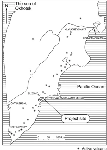
HOT WATER SUPPLY TEST USING GEOTHERMAL HEAT PUMP SYSTEMS AT PETROPAVLOVSK-KAMCHATSKY,
THE CAPITAL OF KAMCHATKA, RUSSIA
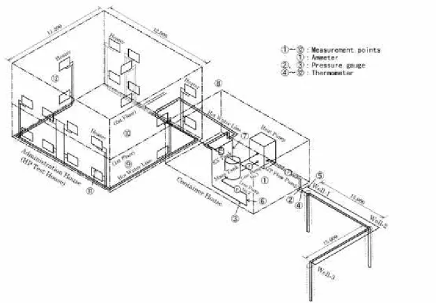
This potential test facility consisted of the sanatorium administration building and the accommodation building. The administration building was under construction and thus the piping work and compliance with the heating conditions were facilitated. This means that the capacity of the GHP is not sufficient for all the rooms of the administration building.
CURRENT STATUS AND FUTURE DIRECTIONS OF GEOTHERMAL HEAT PUMPS IN TURKEY
Based on the data given by the "Firm B", six projects were implemented for building heating ranging from an air-conditioned floor area of 650 m2 to 24,900 m2 by means of GSHPs. In fact, no reliable data has been obtained from "Firm B" and it is understood that this firm has gone bankrupt. Therefore, only data given by the "Firm D", which is currently the only one in installing GSHPs in Turkey, was taken into account.
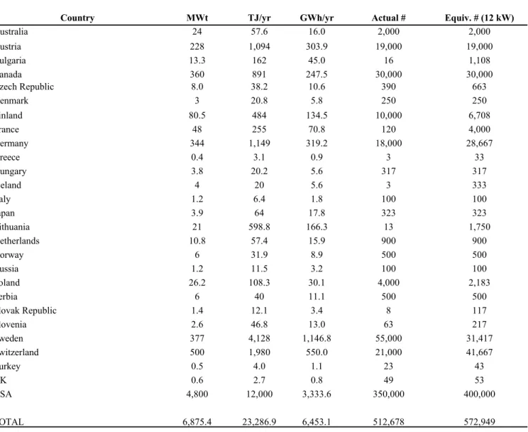
The size of the individual units is in the range of 9 to 46 kW and 38 to 46 for residential and commercial uses respectively. Of the GHP systems installed so far, 80% were vertical ground-connected GHP systems while about half were designed for both heating and cooling. Most of the installations are in the Marmara region (in the province of Istanbul).
In this context, energy, which can be defined as money and even cash from the point of view of energy efficiency, is the mainstay of modern society. However, in Turkey, the design does not take into account this cost reduction factor, which can be achieved by reducing the necessary length of the ground loop with the optimal selection of the backfill material. This is an abridged version of the paper presented at the 26th Workshop on Geothermal Reservoir Engineering, Stanford University, CA, January 2001.
Heating and cooling a room using a ground-connected vertical GSHP (in Turkish), Ege University Research Fund Project (unpublished).
DESIGN ASPECTS OF COMMERCIAL OPEN-LOOP HEAT PUMP SYSTEMS
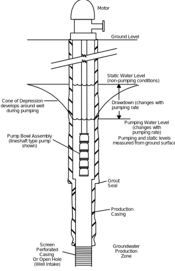
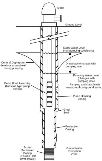
This level is indicative of the water table in unconfined (or aquifers) or the piezometric level in a confined (or artesian) aquifer and is known as the static water level (SWL). The subsidence at a given rate is the manifestation, at the well, of the cone of depression that forms in the aquifer around the well during pumping. A key part of the design process is the determination of the well pump power required for a range of groundwater flow rates.
Results from these wells can also provide useful information for new well design. This is especially true if an injection well is to be used for water disposal. This is characteristic of well pumping applications and results from the large influence of the lift component.
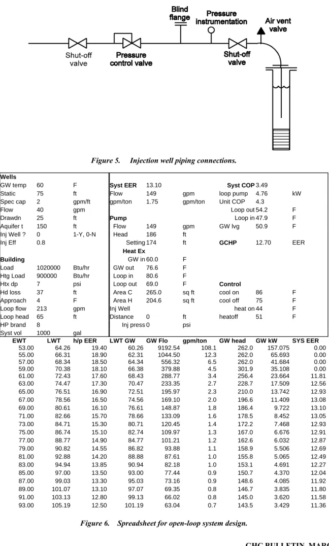
Key components in the connection of the production well to the system are illustrated in Figure 3. These exchangers are key to system reliability as they protect the building loop from exposure to the groundwater. The presence of the exchanger essentially eliminates water quality limitations for the use of open loop.
The greater the operating time of the system, the easier it is to justify the added value.
The table in the lower part of the figure indicates the calculations for the cooling mode. The spreadsheet is configured to look at the cooling load as the primary load and it selects the peak EER value from the table and displays it along with the groundwater flow in the output section. Heat exchanger data includes the cooling mode and leave temperatures at the peak condition along with calculated surface area requirements in the heating and cooling modes.
These area values are not intended to be specified to the vendor, but are used to give the designer an indication of which mode (heating or cooling) is dominant in the system design. If an injection well is specified in the input, the spreadsheet calculates, using the aquifer thickness and flow rate, a separation distance requirement for the production and injection wells. All values shown are based on an assumed heat exchanger approach as specified in the input.
Finally, the set temperature for the well pump in heating and cooling modes is displayed based on the system volume specified in the input. These provide a clearer indication of system performance in the various modes and allow the designer to evaluate the impact of operating at other than the highest performance selected by the spreadsheet. Despite their long history of use and perceived simplicity, care is required in design and installation for the systems' full potential to be achieved.
KNOW THE RULES - verify groundwater regulatory issues DO YOUR ELECTRICAL work - previous groundwater experience in the area, other wells.
SPECIFICATION OF WATER WELLS
The lower part of the well in the production zone can be completed with only a well (in rock formations), a screen or a screen and an artificial filter (gravel plug), depending on the nature of the aquifer materials. A second well casing is sometimes installed in the upper part of the well to accommodate the installation of the surface seal. Samples from the production zone of the well are what make decisions about screen slot size and the grade of gravel bit required for completion.
Plumbing (deviation from vertical) and alignment (“straightness”) of the well are important issues. 27. If used, the screen would be attached to the bottom of the pump body housing. The diameter of the pump casing is a function of the pump to be stimulated in the well.
The screen plays a critical role in the performance of the well as it provides filtration of the water entering the well. As in the case of the screen slot size selection, the determination of the gravel pack parameters is based on the cutting sieve analysis results. Placement of the gravels is generally achieved by either pouring from the surface (in shallow wells) or by placing them through a tremie (in wells greater than 300 m depth) (Roscoe Moss Company, 1985).
The specification describes the size of the sample and the type of container it will be stored in (usually a container supplied by the laboratory performing the analysis) and when the sample should be taken (after 1 hour of pump operation).
A GUIDE TO ON-LINE GEOLOGICAL INFORMATION AND PUBLICATIONS FOR USE IN GSHP SITE
CHARACTERIZATION
The USGS site http://search.usgs.gov/ contains a similar interactive map of the US (click on the USGS state-by-state link to access). Online maps of both bedrock and superficial geology, accessible by clicking Maps and Digital Data on the first page of the site. The regulatory functions of water wells are the responsibility of the Department of Environmental Conservation, Division of Water.
Access the report by clicking on Publications and Product Information at the top of the page, then Featured Tennessee Publications, and then the report title. General Geology of Virginia (accessed by clicking on the phrase at the top of the first page) explains the general geology and physiographic regions of the state. Click on more information on MN geology on the front page of the site, point to maps, then the map title.
More detailed information on both the bedrock and the Quaternary geology of the state is available in two online (and downloadable) publications. Click on more information about MN geology on the first page and then Minnesota at a glance and then the title of the publication (in Adobe Acrobat). Click on more information about MN geology, regional information and then the title of the document.
Ranking and general information by clicking on the CWI link on the front page of the site.
DUAL-SET POINT CONTROL OF OPEN-LOOP HEAT PUMP SYSTEMS
At loads less than maximum, the well pump cycles in response to the magnitude of the load. Based on the thermal mass of the system and the thermal load of the loop, the operating range of the well pump is set around the optimum temperature in the prevailing mode (usually cooling). The building loop return temperature is most commonly used for well pump control.
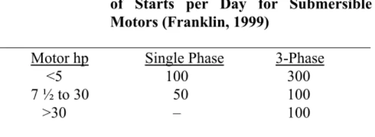
The size of the range between these two values is a function of the thermal mass of the system (liters of water per peak block ton [liters of water per peak block kW]) and the allowable time between starts for the well pump motor. In the context of the heat pump system, a more useful unit would be 15 minutes between starts. The range between these two temperatures must be sufficient, given the thermal mass of the loop and the load placed on it, to accommodate the 15-minute limit between starts.
Naturally, the thermal mass of the building loop is constant, as is the capacity of the groundwater (via the heat exchanger) to remove heat from the circuit. As a result, the primary variable in terms of time between pump starts is the building's thermal load applied to the loop. The water in the branch line to the idle heat pumps is not available to contribute to the thermal mass of the system for well pump cycling calculations.
The thermal mass of the system used in the development of the guidelines in this paper only considers the water volume.