DIPLOMADO DE PROFUNDIZACION PRUEBA DE HABILIDADES PRACTICAS CISCO
EMEL ANTONIO VILORIA GAMEZ
UNIVERSIDAD NACIONAL ABIERTA Y A DISTANCIA
ESCUELA DE CIENCIAS BASICAS, TECNOLOGIA E INGENIERIA INGENIERIA DE TELECOMUNICACIONES
DIPLOMADO DE PROFUNDIZACION PRUEBA DE HABILIDADES PRACTICAS CISCO
EMEL ANTONIO VILORIA GAMEZ
Diplomado de opción de grado presentado para optar el título de INGENIERO DE TELECOMUNICACIONES
DIRECTOR:
MSc. GERARDO GRANADOS ACUÑA
UNIVERSIDAD NACIONAL ABIERTA Y A DISTANCIA
ESCUELA DE CIENCIAS BASICAS, TECNOLOGIA E INGENIERIA INGENIERIA DE TELECOMUNICACIONES
NOTA DE ACEPTACIÓN
Presidente del Jurado
Jurado
Jurado
AGRADECIMIENTOS
Doy gracias a Dios primeramente por la salud, sabiduría, dirección y entendimiento que me ha dado para hacer posible estos sueños, a mi familia que me ha apoyado y motivado en todos los aspectos para alcanzar con dedicación las metas propuestas en mi formación profesional.
A mi tutor Gerardo Granados Acuña, por estar siempre dispuesto a orientarme y aclarar todas mis dudas en cada tutoría durante este proceso de formación en CCNP.
TABLA DE CONTENIDO
AGRADECIMIENTOS ... 4
LISTA DE TABLAS ... 6
LISTA DE FIGURAS ... 7
GLOSARIO ... 8
RESUMEN ... 9
ABSTRACT... 9
INTRODUCCIÓN ... 10
DESARROLLO DE LA ACTIVIDAD ... 11
1. Escenario 1. ... 11
2. Escenario 2. ... 27
3. Escenario 3. ... 34
CONCLUSIONES ... 50
LISTA DE TABLAS
Tabla 1. Interfaces de Loopback en R1 ... 18
Tabla 2. Interfaces de Loopback en R5 ... 20
Tabla 3. Información configuración R1 ... 27
Tabla 4. Información configuración R2 ... 27
Tabla 5. Información configuración R3 ... 28
Tabla 6. Información configuración R4 ... 28
Tabla 7. VLAN y configure las direcciones IP ... 43
LISTA DE FIGURAS
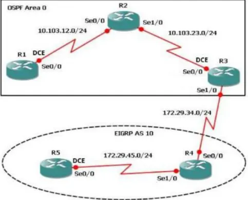
Figura 1. Escenario 1 ... 11
Figura 2. Verificación Loopback en R3 ... 22
Figura 3. Verificación de rutas del sistema autónomo opuesto en su tabla de enrutamiento mediante el comando show ip route en R1 ... 25
Figura 4. Verificación de rutas del sistema autónomo opuesto en su tabla de enrutamiento mediante el comando show ip route en R5 ... 26
Figura 5.Escenario 2 ... 27
Figura 6. Presentación paso con los comandos utilizados y la salida del comando show ip route... 29
Figura 7. Presentación paso con los comandos utilizados y la salida del comando show ip route 2 ... 30
Figura 8. Presentación paso con los comandos utilizados y la salida del comando show ip route 3 ... 31
Figura 9. Presentación paso con los comandos utilizados y la salida del comando show ip bgp ... 33
Figura 10. Escenario 3 ... 34
Figura 11. Verificación de las configuraciones mediante el comando show vtp status ... 36
Figura 12. Verificación de las configuraciones mediante el comando show vtp status 2 ... 36
Figura 13. Verificación de las configuraciones mediante el comando show vtp status 3 ... 37
Figura 14. Verificación del estado del enlace trunk en SWT1 ... 38
Figura 15. Verificación del estado del enlace trunk en SWT2 ... 39
Figura 16. Verificación del estado del enlace trunk en SWT1 ... 40
GLOSARIO
PROTOCOLO: para la informática y la telecomunicación, un protocolo de comunicaciones es el conjunto de reglas y estándares que tienen como fin controlar las secuencias de los mensajes que suceden en una comunicación entre las entidades que forman parte de una misma red.
RED: la red informática nombra al conjunto de computadoras y otros equipos interconectados, que comparten información, recursos y servicios. Puede a su vez dividirse en diversas categorías, según su alcance (red de área local o LAN, red de área metropolitana o MAN, red de área amplia o WAN, etc.), su método de conexión (por cable coaxial, fibra óptica, radio, microondas, infrarrojos) o su relación funcional (cliente-servidor, persona a persona), entre otras.
SWITCH: los switches son dispositivos digitales lógicos de interconexión de equipos que operan en la capa de enlace de datos del modelo OSI. Su función es interconectar dos o más host de manera similar a los puentes de red, pasando datos de un segmento a otro de acuerdo con la dirección MAC de destino de las tramas en la red y eliminando la conexión una vez finalizada ésta.
CCNP: este curriculum avanzado capacita a los estudiantes para instalar, configurar y operar redes locales y de área amplia, y para brindar servicios de acceso por marcación a organizaciones que tienen redes desde 100 hasta 500 nodos con protocolos y tecnologías tales como TCP/IP, OSPF, EIGRP, BGP, ISDN, Frame Relay, STP y VTP a lo largo de 2 cursos: Route Avanzado, Switch Avanzado
RESUMEN
El programa de estudios Cisco CCNP ofrece una experiencia de aprendizaje con una gran carga tanto teórica como práctica que abarca habilidades avanzadas de Routing, Switching y resolución de problemas. En el siguiente trabajo se realizará el paso a paso de dos configuraciones en packet tracer los cuales corresponde a la prueba de habilidades practicas del diplomado CISCO CCNP, cada uno de los pasos anteriormente mencionados constaran de tres escenarios que abarcan en gran parte los conocimientos adquiridos y permiten reforzar lo aplicado durante el programa. Está conformado en gran parte por el código aplicado a la configuración de cada escenario y únicamente se presentan imágenes para demostrar el funcionamiento a través de show ip route, show vlan, show ip bgp, etc.
Palabras Clave: Redes, Telecomunicaciones, CISCO, CCNP
ABSTRACT
The Cisco CCNP curriculum offers a highly loaded theoretical and practical learning experience that encompasses advanced Routing, Switching and problem solving skills. In the following work will be carried out step by step of two configurations in packet tracer which corresponds to the test of practical skills of the CISCO CCNP diploma, each of the steps mentioned above will consist of three scenarios that largely cover the knowledge acquired and allow to reinforce what was applied during the program. It is shaped in large part by the code applied to the configuration of each scenario and only images are presented to demonstrate the operation through show ip route, show vlan, show ip bgp, etc.
INTRODUCCIÓN
El programa de estudios Cisco CCNP está diseñado para alumnos que quieran adquirir habilidades de gestión de redes destinadas a operar en el mundo profesional y de nivel empresarial. CCNP ayuda a los alumnos a desarrollar las habilidades necesarias para complementar con éxito títulos universitarios relacionados con las TIC y para prepararse para la certificación Cisco CCNP.
DESARROLLO DE LA ACTIVIDAD
1. Escenario 1.
1.1. Aplique las configuraciones iniciales y los protocolos de enrutamiento para los routers R1, R2, R3, R4 y R5 según el diagrama. No asigne passwords en los routers. Configurar las interfaces con las direcciones que se muestran en la topología de red.
Se configura R1 de acuerdo a las condiciones iniciales.
Router>enable
Router#configure terminal
Enter configuration commands, one per line. End with CNTL/Z. Router(config)#no ip domain-lookup
Router(config)#line con 0
Router(config-line)#logging synchronous Router(config-line)#exec-timeout 0 0
Router(config-line)#exit
Router(config)#interface loopback 1
Router(config-if)#
%LINK-5-CHANGED: Interface Loopback1, changed state to up
%LINEPROTO-5-UPDOWN: Line protocol on Interface Loopback1, changed state o up
Router(config-if)#interface serial 0/0/1
Router(config-if)#ip address 10.103.12.2 255.255.255.0 Router(config-if)#clock rate 128000
Router(config-if)#no shutdown
Router(config-if)#
%LINK-5-CHANGED: Interface Serial0/0/1, changed state to up
Router(config-if)#exit Router(config)#exit Router#
%SYS-5-CONFIG_I: Configured from console by console
Router# Router(config)#router ospf 1 Router(config-router)#router-id 1.1.1.1
Router(config-router)#network 10.1.0.0 0.0.3.255 area 0 Router(config-router)#network 10.103.12.0 0.0.0.255 area 0 Router#
%SYS-5-CONFIG_I: Configured from console by console
%LINEPROTO-5-UPDOWN: Line protocol on Interface Serial0/0/1, changed state to up
Router#Router#copy ru st
Destination filename [startup-config]? Building configuration...
[OK] Router#
Router>enable
Router#configure terminal
Enter configuration commands, one per line. End with CNTL/Z. Router(config)#no ip domain-lookup
Router(config)#line con 0
Router(config-line)#logging synchronous Router(config-line)#exec-timeout 0 0 Router(config-line)#exit
Router(config)#interface loopback 2
Router(config-if)#
%LINK-5-CHANGED: Interface Loopback2, changed state to up
%LINEPROTO-5-UPDOWN: Line protocol on Interface Loopback2, changed state to up
Router(config-if)#interface serial 0/0/0
Router(config-if)#ip address 10.103.12.1 255.255.255.0 Router(config-if)#no shut
Router(config-if)#
%LINK-5-CHANGED: Interface Serial0/0/0, changed state to up
Router(config-if)#interface serial 0/0/1
%LINEPROTO-5-UPDOWN: Line protocol on Interface Serial0/0/0, changed state to up
Router(config-if)#interface serial 0/0/1
Router(config-if)#ip address 10.103.23.2 255.255.255.0 Router(config-if)#no shut
Router(config-if)#
%LINK-5-CHANGED: Interface Serial0/0/1, changed state to up
Router(config-if)#exit Router(config)#exit Router# Router(config)#router ospf 1
Router(config-router)#router-id 2.2.2.2
Router(config-router)#network 10.103.12.0 0.0.0.255 area 0 Router(config-router)#network 10.103.23.0 0.0.0.255 area 0 Router#
Router#copy
%LINEPROTO-5-UPDOWN: Line protocol on Interface Serial0/0/1, changed state to up
Router#copy ru st
Destination filename [startup-config]? Building configuration...
[OK] Router#
Luego, se realiza la configuración R3 y sus configuraciones inciales.
Router>enable Router#configure terminal
Enter configuration commands, one per line. End with CNTL/Z. Router(config)#no ip domain-lookup
Router(config)#line con 0
Router(config-line)#logging synchronous Router(config-line)#exec-timeout 0 0 Router(config-line)#exit
Router(config)#interface lookback 3
% Invalid input detected at '^' marker. Router(config)#interface loopback 3
Router(config-if)#
%LINK-5-CHANGED: Interface Loopback3, changed state to up
%LINEPROTO-5-UPDOWN: Line protocol on Interface Loopback3, changed state to up
Router(config-if)#interface serial 0/0/0
Router(config-if)#ip address 10.103.23.1 255.255.255.0 Router(config-if)#clock rate 128000
Router(config-if)#no shutdown
Router(config-if)#
%LINK-5-CHANGED: Interface Serial0/0/0, changed state to up
Router(config-if)#exit Router(config)#int
to up
Router(config)#interface loopback 3 Router(config-if)#interface serial 0/0/1
Router(config-if)#ip address 172.29.34.2 255.255.255.0 Router(config-if)#no shutdown
Router(config-if)#
%LINK-5-CHANGED: Interface Serial0/0/1, changed state to up
Router(config-if)#exit Router(config)#exit Router#
Router#
Router(config)#router ospf 1
Router(config-router)#router-id 3.3.3.3
Router(config-router)#network 10.103.23.0 0.0.0.255 area 0 Router#
%SYS-5-CONFIG_I: Configured from console by console
Router#copy ru
%LINEPROTO-5-UPDOWN: Line protocol on Interface Serial0/0/1, changed state to up
Router#copy ru st
Destination filename [startup-config]? Building configuration...
[OK] Router#
Seguido de la configuración R4 y sus condiciones iniciales.
Router>enable
Router#configure terminal
Enter configuration commands, one per line. End with CNTL/Z. Router(config)#no ip domain-lookup
Router(config)#line con 0
Router(config-line)#logging synchronous Router(config-line)#exec-timeout 0 0 Router(config-line)#exit
Router(config-if)#
%LINK-5-CHANGED: Interface Loopback4, changed state to up
%LINEPROTO-5-UPDOWN: Line protocol on Interface Loopback4, changed state to up
Router(config-if)#interface serial 0/0/0
Router(config-if)#ip address 172.29.34.1 255.255.255.0 Router(config-if)#no shut
Router(config-if)#
%LINK-5-CHANGED: Interface Serial0/0/0, changed state to up
Router(config-if)#interface serial 0/0/
%LINEPROTO-5-UPDOWN: Line protocol on Interface Serial0/0/0, changed state to up
1
Router(config-if)#interface serial 0/0/1
Router(config-if)#ip address 172.29.45.2 255.255.255.0 Router(config-if)#no shut
Router(config-if)#
%LINK-5-CHANGED: Interface Serial0/0/1, changed state to up
Router(config-if)#exit Router(config)#exit Router#
%SYS-5-CONFIG_I: Configured from console by console
Router#copy ru st
Destination filename [startup-config]?
%LINEPROTO-5-UPDOWN: Line protocol on Interface Serial0/0/1, changed state to up
Destination filename [startup-config]? Building configuration...
[OK] Router#
Router>enable
Router#configure terminal
Enter configuration commands, one per line. End with CNTL/Z. Router(config)#no ip domain-lookup
Router(config)#line con 0
Router(config-line)#logging synchronous Router(config-line)#exec-timeout 0 0 Router(config-line)#exit
Router(config)#interface loopback 5
Router(config-if)#
%LINK-5-CHANGED: Interface Loopback5, changed state to up
%LINEPROTO-5-UPDOWN: Line protocol on Interface Loopback5, changed state to up
Router(config-if)#interface serial 0/0/0
Router(config-if)#ip address 172.29.45.1 255.255.255.0 Router(config-if)#clock rate 128000
Router(config-if)#no shut
Router(config-if)#
%LINK-5-CHANGED: Interface Serial0/0/0, changed state to up
Router(config-if)#exit Router(config)#exit Router#
%SYS-5-CONFIG_I: Configured from console by console
Router#copy ru st
Destination filename [startup-config]? Building configuration... [OK]
Router#
%LINEPROTO-5-UPDOWN: Line protocol on Interface Serial0/0/0, changed state to up
Router#
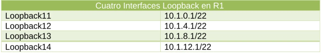
Tabla 1. Interfaces de Loopback en R1
Cuatro Interfaces Loopback en R1
Loopback11 10.1.0.1/22
Loopback12 10.1.4.1/22
Loopback13 10.1.8.1/22
Loopback14 10.1.12.1/22
Configuración Router 1
Router>enable
Router#configure terminal
Enter configuration commands, one per line. End with CNTL/Z. Router(config)#interface loopback11
Router(config-if)#
%LINK-5-CHANGED: Interface Loopback11, changed state to up
%LINEPROTO-5-UPDOWN: Line protocol on Interface Loopback11, changed state to up
Router(config-if)#ip address 10.1.0.1 255.255.252.0 Router(config-if)#exit
Router(config)#interface loopback12
Router(config-if)#
%LINK-5-CHANGED: Interface Loopback12, changed state to up
%LINEPROTO-5-UPDOWN: Line protocol on Interface Loopback12, changed state to up
Router(config-if)#ip address 10.1.4.1 255.255.252.0 Router(config-if)#exit
Router(config)#interface loopback13
Router(config-if)#
%LINK-5-CHANGED: Interface Loopback13, changed state to up
%LINEPROTO-5-UPDOWN: Line protocol on Interface Loopback13, changed state to up
Router(config)#interface loopback14
Router(config-if)#
%LINK-5-CHANGED: Interface Loopback14, changed state to up
%LINEPROTO-5-UPDOWN: Line protocol on Interface Loopback14, changed state to up
Router(config-if)#ip address 10.1.12.1 255.255.252.0 Router(config-if)#exit
Router(config)#router ospf 1
Router(config-router)#router-id 1.1.1.1
Router(config-router)#network 10.1.0.0 0.0.3.255 area 0 Router(config-router)#network 10.103.12.0
Router#
%SYS-5-CONFIG_I: Configured from console by console
Router#configure terminal
Enter configuration commands, one per line. End with CNTL/Z. Router(config)#router ospf 1
Router(config-router)#network 10.103.12.0 0.0.0.255 area 0 Router(config-router)#exit
Router(config)#exit Router#
%SYS-5-CONFIG_I: Configured from console by console
Router#copy ru st
Destination filename [startup-config]? Building configuration...
[OK] Router#
Router#
Router#configure terminal
Enter configuration commands, one per line. End with CNTL/Z. Router(config)#interface loopback11
Router(config-if)#ip ospf network point-to-point Router(config-if)#exit
Router(config)#interface loopback12
Router(config-if)#ip ospf network point-to-point Router(config-if)#exit
Router(config)#interface loopback13
Router(config-if)#ip ospf network point-to-point Router(config-if)#exit
Router(config-if)#ip ospf network point-to-point Router(config-if)#exit
Router(config)#exit Router#
%SYS-5-CONFIG_I: Configured from console by console
Router#copy ru st
Destination filename [startup-config]? Building configuration...
[OK] Router#
1.3. Cree cuatro nuevas interfaces de Loopback en R5 utilizando la asignación de direcciones 172.5.0.0/22 y configure esas interfaces para participar en el Sistema Autónomo EIGRP 10.
Tabla 2. Interfaces de Loopback en R5
Cuatro Interfaces Loopback en R5
Loopback51 172.5.0.1
Loopback52 172.5.4.1
Loopback53 172.5.8.1
Loopback54 172.5.12.1
Configuración Router 5.
Router>enable
Router#configure terminal
Enter configuration commands, one per line. End with CNTL/Z. Router(config)#interface loopback51
Router(config-if)#
%LINK-5-CHANGED: Interface Loopback51, changed state to up
%LINEPROTO-5-UPDOWN: Line protocol on Interface Loopback51, changed state to up
Router(config-if)#ip address 172.5.0.1 255.255.252.0 Router(config-if)#exit
Router(config)#interface loopback52
Router(config-if)#
%LINEPROTO-5-UPDOWN: Line protocol on Interface Loopback52, changed state to up
Router(config-if)#ip address 172.5.4.1 255.255.252.0 Router(config-if)#exit
Router(config)#interface loopback53
Router(config-if)#
%LINK-5-CHANGED: Interface Loopback53, changed state to up
%LINEPROTO-5-UPDOWN: Line protocol on Interface Loopback53, changed state to up
Router(config-if)#ip address 172.5.8.1 255.255.252.0 Router(config-if)#exit
Router(config)#interface loopback54
Router(config-if)#
%LINK-5-CHANGED: Interface Loopback54, changed state to up
%LINEPROTO-5-UPDOWN: Line protocol on Interface Loopback54, changed state to up
Router(config-if)#ip address 172.5.12.1 255.255.252.0 Router(config-if)#exit
Router(config)#
Router(config)#route eigrp 10 Router(config-router)#auto-summary
Router(config-router)#network 172.5.0.0 0.0.3.255 Router(config-router)#network 172.29.45.0 0.0.0.255
Router#
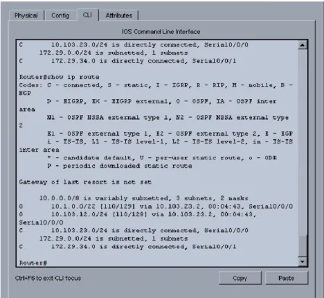
1.5. Configure R3 para redistribuir las rutas EIGRP en OSPF usando el costo de 50000 y luego redistribuya las rutas OSPF en EIGRP usando un ancho de banda T1 y 20,000 microsegundos de retardo.
Router>enable
Router#configure terminal
Enter configuration commands, one per line. End with CNTL/Z. Router(config)#router ospf 10
Router(config-router)#redistribute eigrp 10 subnets Router(config-router)#exit
Router(config)#router ospf 1
Router(config-router)#redistribute eigrp 10 % Only classful networks will be redistributed Router(config-router)#redistribute eigrp 10 subnets Router(config-router)#exit
Router(config)#router eigrp 10
Router(config-router)#redistribute ospf 1 metric 1544 100 255 1 1500 Router(config-router)#exit
Router(config)#exit Router#
%SYS-5-CONFIG_I: Configured from console by console Router#show ip route
Codes: C - connected, S - static, I - IGRP, R - RIP, M - mobile, B - BGP D - EIGRP, EX - EIGRP external, O - OSPF, IA - OSPF inter area
N1 - OSPF NSSA external type 1, N2 - OSPF NSSA external type 2 E1 - OSPF external type 1, E2 - OSPF external type 2, E - EGP i - IS-IS, L1 - IS-IS level-1, L2 - IS-IS level-2, ia - IS-IS inter area - candidate default, U - per-user static route, o - ODR
P - periodic downloaded static route
Gateway of last resort is not set
10.0.0.0/8 is variably subnetted, 3 subnets, 2 masks
O 10.1.0.0/22 [110/129] via 10.103.23.2, 00:08:56, Serial0/0/0 O 10.103.12.0/24 [110/128] via 10.103.23.2, 00:08:56, Serial0/0/0 C 10.103.23.0/24 is directly connected, Serial0/0/0
172.29.0.0/24 is subnetted, 1 subnets
C 172.29.34.0 is directly connected, Serial0/0/1
Router#configure terminal
Enter configuration commands, one per line. End with CNTL/Z. Router(config)#router ospf 1
Router(config-router)#network 172.29.34.0 0.0.0.255 area 0 Router(config-router)#exit
Router(config)#exit Router#
%SYS-5-CONFIG_I: Configured from console by console
Router#show ip route
Codes: C - connected, S - static, I - IGRP, R - RIP, M - mobile, B - BGP D - EIGRP, EX - EIGRP external, O - OSPF, IA - OSPF inter area
N1 - OSPF NSSA external type 1, N2 - OSPF NSSA external type 2 E1 - OSPF external type 1, E2 - OSPF external type 2, E - EGP i - IS-IS, L1 - IS-IS level-1, L2 - IS-IS level-2, ia - IS-IS inter area - candidate default, U - per-user static route, o - ODR
P - periodic downloaded static route
Gateway of last resort is not set
10.0.0.0/8 is variably subnetted, 3 subnets, 2 masks
O 10.103.12.0/24 [110/128] via 10.103.23.2, 00:10:57, Serial0/0/0 C 10.103.23.0/24 is directly connected, Serial0/0/0
172.29.0.0/24 is subnetted, 1 subnets
C 172.29.34.0 is directly connected, Serial0/0/1
Router#configure terminal
Enter configuration commands, one per line. End with CNTL/Z. Router(config)#router ospf 1
Router(config-router)#redistribute eigrp 10 subnets Router(config-router)#log-adjacency-changes Router(config-router)#redistribute eigrp 7 subnets Router(config-router)#network 172.29.45.0 area 0 ^
% Invalid input detected at '^' marker.
Router(config-router)#network 172.29.45.0 0.0.0.255 area 0 Router(config-router)#exit
Router(config)#router eigrp 10
Router(config-router)#redistribute ospf 1 metric 50000 200 255 1 1500 Router(config-router)#auto-summary
Router(config-router)#exit
Router(config)#
2. Escenario 2.
2.1. Información para configuración de los Routers.
Tabla 3. Información configuración R1
R1
Interfaz Dirección IP Máscara
Loopback 0 1.1.1.1 255.0.0.0
Loopback 1 11.1.0.1 255.255.0.0
S 0/0 192.1.12.1 255.255.255.0
Tabla 4. Información configuración R2
R2
Interfaz Dirección IP Máscara
Loopback 0 2.2.2.2 255.0.0.0
Loopback 1 12.1.0.1 255.255.0.0
S 0/0 192.1.12.2 255.255.255.0
E 0/0 192.1.23.2 255.255.255.0
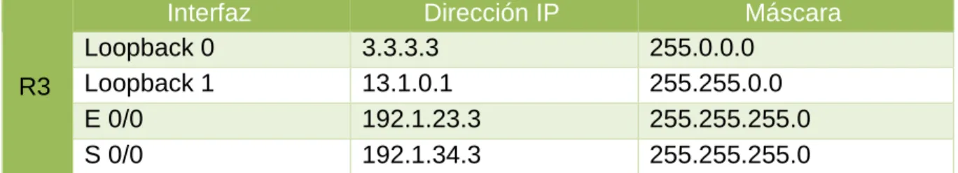
Tabla 5. Información configuración R3
R3
Interfaz Dirección IP Máscara
Loopback 0 3.3.3.3 255.0.0.0
Loopback 1 13.1.0.1 255.255.0.0
E 0/0 192.1.23.3 255.255.255.0
S 0/0 192.1.34.3 255.255.255.0
Tabla 6. Información configuración R4
R4
Interfaz Dirección IP Máscara
Loopback 0 4.4.4.4 255.0.0.0
Loopback 1 14.1.0.1 255.255.0.0
S 0/0 192.1.34.4 255.255.255.0
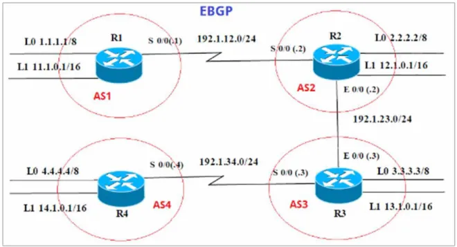
2.2. Configure una relación de vecino BGP entre R1 y R2. R1 debe estar en AS1 y R2 debe estar en AS2. Anuncie las direcciones de Loopback en BGP. Codifique los ID para los routers BGP como 11.11.11.11 para R1 y como 22.22.22.22 para R2. Presente el paso a con los comandos utilizados y la salida del comando show ip route.
AS1#enable
AS1#configure term
Enter configuration commands, one per line. End with CNTL/Z. AS1(config)#router bgp 1
AS1(config-router)#exit AS1(config)#no router bgp 1 AS1(config)#router bgp 1
AS1(config-router)#bgp router-id 11.11.11.11
AS1(config-router)#neighbor 192.1.12.2 remote-as 2 AS1(config-router)#network 1.1.1.1 mask 255.0.0.0 AS1(config-router)#network 11.1.0.1 mask 255.255.0.0 AS1(config-router)#exit
Figura 6. Presentación paso con los comandos utilizados y la salida del comando show ip route
AS2>enable AS2#config term
Enter configuration commands, one per line. End with CNTL/Z. AS2(config)#router bgp 2
AS2(config-router)#neighbor 192.1.12.1 remote-as 1 AS2(config-router)#neighbor 192.1.34.3 remote-as 3 AS2(config-router)#neighbor 192.1.23.3 remote-as 3
AS2(config-router)#%BGP-5-ADJCHANGE: neighbor 192.1.12.1 Up AS2(config-router)#network 1.1.1.0
AS2(config-router)#network 11.1.0.0 AS2(config-router)#exit
AS2(config)#exit AS2#
%SYS-5-CONFIG_I: Configured from console by console
2.3. Configure una relación de vecino BGP entre R2 y R3. R2 ya debería estar configurado en AS2 y R3 debería estar en AS3. Anuncie las direcciones de Loopback de R3 en BGP. Codifique el ID del router R3 como 33.33.33.33. Presente el paso a con los comandos utilizados y la salida del comando show ip route.
AS3>enable AS3#config term
Enter configuration commands, one per line. End with CNTL/Z. AS3(config)#router bgp 3
AS3(config-router)#neighbor 192.1.12.2 remote-as 2 AS3(config-router)#neighbor 192.1.23.2 remote-as 2 AS3#%BGP-5-ADJCHANGE: neighbor 192.1.23.2 Up AS3(config-router)#neighbor 192.1.34.4 remote-as 4 AS3(config-router)#network 4.4.4.4 mask 255.0.0.0 AS3(config-router)#network 14.1.0.1 mask 255.255.0.0 AS3(config-router)#network 2.2.2.2 mask 255.0.0.0 AS3(config-router)#network 12.1.0.1 mask 255.255.0.0 AS3(config-router)#network 3.3.3.3 mask 255.0.0.0 AS3(config-router)#network 13.1.0.1 mask 255.255.0.0 AS3(config-router)#exit
2.4. Configure una relación de vecino BGP entre R3 y R4. R3 ya debería estar configurado en AS3 y R4 debería estar en AS4. Anuncie las direcciones de Loopback de R4 en BGP. Codifique el ID del router R4 como 44.44.44.44. Establezca las relaciones de vecino con base en las direcciones de Loopback Cree rutas estáticas para alcanzar la Loopback 0 del otro router. No anuncie la Loopback 0 en BGP. Anuncie la red Loopback de R4 en BGP. Presente el paso a con los comandos utilizados y la salida del comando show ip route.
AS4>enable AS4#config term
Enter configuration commands, one per line. End with CNTL/Z. AS4(config)#router bgp 4
AS4(config-router)#neighbor 192.1.34.3 remote-as 3
AS4(config-router)#%BGP-5-ADJCHANGE: neighbor 192.1.34.3 Up
AS4(config-router)#neighbor 192.1.23.3 remote-as 3
AS4(config-router)#%BGP-5-ADJCHANGE: neighbor 192.1.23.3 Up
AS4(config-router)#neighbor 192.1.23.2 remote-as 2 AS4(config-router)#neighbor 192.1.12.2 remote-as 2 AS4(config-router)#neighbor 192.1.12.1 remote-as 1
AS4(config-router)#%BGP-5-ADJCHANGE: neighbor 192.1.34.3 Up
AS4(config-router)#network 3.3.3.3 mask 255.0.0.0 AS4(config-router)#network 13.1.0.1 mask 255.255.0.0 AS4(config-router)#network 12.1.0.1 mask 255.255.0.0 AS4(config-router)#network 2.2.2.2 mask 255.0.0.0 AS4(config-router)#network 11.1.0.1 mask 255.255.0.0 AS4(config-router)#network 4.4.4.4 mask 255.0.0.0 AS4(config-router)#network 14.1.0.1 mask 255.255.0.0 AS4(config-router)#exit
AS4(config)#exit AS4#
3. Escenario 3.
3.1. Configurar VTP
3.1.1. Todos los switches se configurarán para usar VTP para las actualizaciones de VLAN. El switch SWT2 se configurará como el servidor. Los switches SWT1 y SWT3 se configurarán como clientes. Los switches estarán en el dominio VPT llamado CCNP y usando la contraseña cisco.
Switch>enable
Switch#config terminal
Enter configuration commands, one per line. End with CNTL/Z. Switch(config)#hostname SWT1
Changing VTP domain name from NULL to CCNP SWT1(config)#vtp version 2
SWT1(config)#vtp mode client
Setting device to VTP CLIENT mode. SWT1(config)#vtp password cisco
Setting device VLAN database password to cisco SWT1(config)#
Switch>enable
Switch#configure terminal
Enter configuration commands, one per line. End with CNTL/Z. Switch(config)#hostname SWT3
SWT3(config)#vtp domain CCNP
Changing VTP domain name from NULL to CCNP SWT3(config)#vtp version 2
SWT3(config)#vtp mode client
Setting device to VTP CLIENT mode. SWT3(config)#vtp password cisco
Setting device VLAN database password to cisco SWT3(config)#
Switch>enable Switch#configure terminal
Enter configuration commands, one per line. End with CNTL/Z. Switch(config)#hostname SWT2
SWT2(config)#vtp domain CCNP
Changing VTP domain name from NULL to CCNP SWT2(config)#vtp version 2
SWT2(config)#vtp mode server Device mode already VTP SERVER. SWT2(config)#vtp password cisco
Setting device VLAN database password to cisco SWT2(config)#
Figura 11. Verificación de las configuraciones mediante el comando show vtp status
3.2. Configurar DTP (Dynamic Trunking Protocol)
3.2.1. Configure un enlace troncal ("trunk") dinámico entre SWT1 y SWT2. Debido a que el modo por defecto es dynamic auto, solo un lado del enlace debe configurarse como dynamic desirable.
SWT1>enable SWT1#conf term
Enter configuration commands, one per line. End with CNTL/Z. SWT1(config)#interface fa
SWT1(config)#interface fastEthernet 0/1
SWT1(config-if)#switchport mode dynamic desirable
SWT1(config-if)#
%LINEPROTO-5-UPDOWN: Line protocol on Interface FastEthernet0/1, changed state to up
%LINEPROTO-5-UPDOWN: Line protocol on Interface FastEthernet0/1, changed state to down
%LINEPROTO-5-UPDOWN: Line protocol on Interface FastEthernet0/1, changed state to up
3.2.2. Verifique el enlace "trunk" entre SWT1 y SWT2 usando el comando show interfaces trunk.
3.2.3. Entre SWT1 y SWT3 configure un enlace "trunk" estático utilizando el comando switchport mode trunk en la interfaz F0/3 de SWT1
SWT1>enable
SWT1#configure terminal
Enter configuration commands, one per line. End with CNTL/Z. SWT1(config)#interface fa
SWT1(config)#interface fastEthernet 0/3 SWT1(config-if)#switchport mode trunk
SWT1(config-if)#
%LINEPROTO-5-UPDOWN: Line protocol on Interface FastEthernet0/3, changed state to down
%LINEPROTO-5-UPDOWN: Line protocol on Interface FastEthernet0/3, changed state to up
3.2.4. Verifique el enlace "trunk" el comando show interfaces trunk en SWT1.
3.2.5. Configure un enlace "trunk" permanente entre SWT2 y SWT3.
SWT2>enable
SWT2#configure terminal
Enter configuration commands, one per line. End with CNTL/Z. SWT2(config)#interface fa
SWT2(config)#interface fastEthernet 0/3
SWT2(config-if)#switchport mode trunk
SWT2(config-if)#
%LINEPROTO-5-UPDOWN: Line protocol on Interface FastEthernet0/3, changed state to down
%LINEPROTO-5-UPDOWN: Line protocol on Interface FastEthernet0/3, changed state to up
SWT2(config-if)#exit SWT2(config)#
SWT3>enable
%LINEPROTO-5-UPDOWN: Line protocol on Interface FastEthernet0/1, changed state to down
%LINEPROTO-5-UPDOWN: Line protocol on Interface FastEthernet0/1, changed state to up
SWT3#configure terminal
Enter configuration commands, one per line. End with CNTL/Z. SWT3(config)#interface fa
SWT3(config)#interface fastEthernet 0/1 SWT3(config-if)#switchport mode trunk SWT3(config-if)#exit
SWT3(config)#end SWT3#
3.3. Agregar VLANs y asignar puertos.
3.3.1. En STW1 agregue la VLAN 10. En STW2 agregue las VLANS Compras (10), Mercadeo (20), Planta (30) y Admon (99).
En STW1
SWT1>enable
SWT1#configure terminal
Enter configuration commands, one per line. End with CNTL/Z. SWT1(config)#vlan 10
VTP VLAN configuration not allowed when device is in CLIENT mode. SWT1(config)#
En STW2
SWT2#configure terminal
Enter configuration commands, one per line. End with CNTL/Z. SWT2(config)#vlan 10
SWT2(config-vlan)#name Compras SWT2(config-vlan)#vlan 20
SWT2(config-vlan)#name Mercadeo SWT2(config-vlan)#vlan 30
SWT2(config-vlan)#name Planta SWT2(config-vlan)#vlan 99 SWT2(config-vlan)#name Admon SWT2(config-vlan)#exit
SWT2(config)#
3.3.2. Verifique que las VLANs han sido agregadas correctamente.
En SWT1: No se pude crear la vlan 10 ya que en el switch 1 tiene un vtp en modo cliente, lo que no permite crear la Vlan.
En SWT2:
3.3.3. Asocie los puertos a las VLAN y configure las direcciones IP de acuerdo con la siguiente tabla.
Tabla 7. VLAN y configure las direcciones IP
Interfaz VLAN Direcciones IP de los PCs
F0/10 VLAN 10 190.108.10.X / 24
F0/15 VLAN 20 190.108.20.X /24
F0/20 VLAN 30 190.108.30.X /24
X = número de cada PC particular
En SWT1.
SWT1>enable
SWT1#configure terminal
Enter configuration commands, one per line. End with CNTL/Z. SWT1(config)#interface vlan 10
SWT1(config-if)#
%LINK-5-CHANGED: Interface Vlan10, changed state to up
%LINEPROTO-5-UPDOWN: Line protocol on Interface Vlan10, changed state to up
SWT1(config-if)#ip address 190.108.10.1 255.255.255.0 SWT1(config-if)#exit
SWT1(config)#interface vlan 20 SWT1(config-if)#
%LINK-5-CHANGED: Interface Vlan20, changed state to up
%LINEPROTO-5-UPDOWN: Line protocol on Interface Vlan20, changed state to up
SWT1(config-if)#ip address 190.108.20.1 255.255.255.0 SWT1(config-if)#exit
SWT1(config)#interface vlan 30 SWT1(config-if)#
%LINK-5-CHANGED: Interface Vlan30, changed state to up
SWT1(config-if)#ip address 190.108.30.1 255.255.255.0 SWT1(config-if)#exit
En SWT2.
SWT2>enable
SWT2#configure terminal
Enter configuration commands, one per line. End with CNTL/Z. SWT2(config)#interface vlan 10
SWT2(config-if)#ip address 190.108.10.2 255.255.255.0 SWT2(config-if)#exit
SWT2(config)#interface vlan 20
SWT2(config-if)#ip address 190.108.20.2 255.255.255.0 SWT2(config-if)#exit
SWT2(config)#interface vlan 30
SWT2(config-if)#ip address 190.108.30.2 255.255.255.0 SWT2(config-if)#exit
En SWT3
SWT3>enable
SWT3#configure terminal
Enter configuration commands, one per line. End with CNTL/Z. SWT3(config)#interface vlan 10
SWT3(config-if)#
%LINK-5-CHANGED: Interface Vlan10, changed state to up
%LINEPROTO-5-UPDOWN: Line protocol on Interface Vlan10, changed state to up
SWT3(config-if)#ip address 190.108.10.3 255.255.255.0 SWT3(config-if)#exit
SWT3(config)#interface vlan 20 SWT3(config-if)#
%LINK-5-CHANGED: Interface Vlan20, changed state to up
%LINEPROTO-5-UPDOWN: Line protocol on Interface Vlan20, changed state to up
SWT3(config-if)#ip address 190.108.20.3 255.255.255.0 SWT3(config-if)#exit
%LINK-5-CHANGED: Interface Vlan30, changed state to up
%LINEPROTO-5-UPDOWN: Line protocol on Interface Vlan30, changed state to up
SWT3(config-if)#ip address 190.108.30.3 255.255.255.0 SWT3(config-if)#exit
3.3.4. Configure el puerto F0/10 en modo de acceso para SWT1, SWT2 y SWT3 y asígnelo a la VLAN 10.
En SWT1.
SWT1>enable
SWT1#configure terminal
Enter configuration commands, one per line. End with CNTL/Z. SWT1(config)#interface fa
SWT1(config)#interface fastEthernet 0/10 SWT1(config-if)#switchport mode access SWT1(config-if)#switchport access vlan 10 SWT1(config-if)#exit
SWT1(config)#exit SWT1#
%SYS-5-CONFIG_I: Configured from console by console
En SWT2.
SWT2(config)#interface fa
SWT2(config)#interface fastEthernet 0/10 SWT2(config-if)#switchport mode access SWT2(config-if)#switchport access vlan 10 SWT2(config-if)#exit
SWT2(config)# SWT2#
En SWT3.
SWT3#configure terminal
Enter configuration commands, one per line. End with CNTL/Z.. SWT3(config)#interface fa
SWT3(config)#interface fastEthernet 0/10 SWT3(config-if)#switchport mode access SWT3(config-if)#switchport access vlan 10 SWT3(config-if)#exit
SWT3(config)#exit SWT3#
%SYS-5-CONFIG_I: Configured from console by console SWT3#
3.3.5. Repita el procedimiento para los puertos F0/15 y F0/20 en SWT1, SWT2 y SWT3. Asigne las VLANs y las direcciones IP de los PCs de acuerdo con la tabla de arriba.
En SWT1.
SWT1>enable
SWT1#configure terminal
Enter configuration commands, one per line. End with CNTL/Z. SWT1(config)#interface fa
SWT1(config)#interface fastEthernet 0/15 SWT1(config-if)#switchport mode access SWT1(config-if)#switchport access vlan 20 SWT1(config-if)#exit
SWT1(config)#interface fa
SWT1(config)#interface fastEthernet 0/20 SWT1(config-if)#switchport mode access SWT1(config-if)#switchport access vlan 30 SWT1(config-if)#exit
SWT1(config)#exit SWT1#
%SYS-5-CONFIG_I: Configured from console by console
En SWT2
SWT2#configure terminal
Enter configuration commands, one per line. End with CNTL/Z. SWT2(config)#interface fa
SWT2(config)#interface fastEthernet 0/15 SWT2(config-if)#switchport mode access SWT2(config-if)#switchport access vlan 20 SWT2(config-if)#no shut
SWT2(config-if)#exit SWT2(config)#interface fa
SWT2(config)#interface fastEthernet 0/20 SWT2(config-if)#switchport mode access SWT2(config-if)#switchport access vlan 30 SWT2(config-if)#end
SWT2#
%SYS-5-CONFIG_I: Configured from console by console
En SWT3
SWT3>enable
SWT3#configure terminal
Enter configuration commands, one per line. End with CNTL/Z. SWT3(config)#interface fa
SWT3(config)#interface fastEthernet 0/15 SWT3(config-if)#switchport mode access SWT3(config-if)#switchport access vlan 20 SWT3(config-if)#exit
SWT3(config)#interface fa
SWT3(config)#interface fastEthernet 0/20 SWT3(config-if)#switchport mode access SWT3(config-if)#switchport access vlan 30 SWT3(config-if)#exit
SWT3(config)#exit SWT3#
%SYS-5-CONFIG_I: Configured from console by console
3.4. Configurar las direcciones IP en los Switches.
3.4.1. En cada uno de los Switches asigne una dirección IP al SVI (Switch Virtual
Interface) para VLAN 99 de acuerdo con la siguiente tabla de direccionamiento y
Tabla 8. Configurar las direcciones IP en los switches
Equipo Interfaz Dirección IP Máscara
SWT1 VLAN 99 190.108.99.1 255.255.255.0
SWT2 VLAN 99 190.108.99.2 255.255.255.0
SWT3 VLAN 99 190.108.99.3 255.255.255.0
En SWT1.
SWT1>enable
SWT1#config terminal
Enter configuration commands, one per line. End with CNTL/Z. SWT1(config)#interface vlan99
SWT1(config-if)#
%LINK-5-CHANGED: Interface Vlan99, changed state to up
%LINEPROTO-5-UPDOWN: Line protocol on Interface Vlan99, changed state to up
SWT1(config-if)#ip address 190.108.99.1 255.255.255.0 SWT1(config-if)#exit
SWT1(config)#
En SWT2.
SWT2>enable
SWT2#configure terminal
Enter configuration commands, one per line. End with CNTL/Z. SWT2(config)#interface vlan 99
SWT2(config-if)#
%LINK-5-CHANGED: Interface Vlan99, changed state to up
%LINEPROTO-5-UPDOWN: Line protocol on Interface Vlan99, changed state to up
SWT2(config-if)#ip address 190.108.99.2 255.255.255.0 SWT2(config-if)#exit
SWT3>enable
SWT3#configure terminal
Enter configuration commands, one per line. End with CNTL/Z. SWT3(config)#interface vlan 99
SWT3(config-if)#
%LINK-5-CHANGED: Interface Vlan99, changed state to up
%LINEPROTO-5-UPDOWN: Line protocol on Interface Vlan99, changed state to up
SWT3(config-if)#ip address 190.108.99.3 255.255.255.0 SWT3(config-if)#exit
SWT3(config)#end SWT3#
%SYS-5-CONFIG_I: Configured from console by console SWT3#
3.5. Verificar la conectividad Extremo a Extremo
3.5.1. Ejecute un Ping desde cada PC a los demás. Explique por qué el ping tuvo o no tuvo éxito.
RESPUESTA: El ping entre PCs es exitoso porque están dentro de la misma vlan. En caso de tratar de hacer ping entre una vlans diferentes no es posible.
3.5.2. Ejecute un Ping desde cada Switch a los demás. Explique por qué el ping tuvo o no tuvo éxito.
RESPUESTA: Al ejecutar un ping de cada ping a los demás es correcto, porque la vlan 99 está asignada, por tanto, al realizar ping entre switchs, usando las direcciones ip asignadas en su respectiva sección es satisfactorio.
3.5.3. Ejecute un Ping desde cada Switch a cada PC. Explique por qué el ping tuvo o no tuvo éxito.
CONCLUSIONES
BIBLIOGRAFIA
Teare, D., Vachon B., Graziani, R. (2015). CISCO Press (Ed). Basic Network and Routing Concepts. Implementing Cisco IP Routing (ROUTE) Foundation Learning Guide CCNP ROUTE 300-101. Recuperado de https://1drv.ms/b/s!AmIJYei-NT1IlnMfy2rhPZHwEoWx
Teare, D., Vachon B., Graziani, R. (2015). CISCO Press (Ed). EIGRP Implementation. Implementing Cisco IP Routing (ROUTE) Foundation Learning Guide CCNP ROUTE 300-101. Recuperado de https://1drv.ms/b/s!AmIJYei-NT1IlnMfy2rhPZHwEoWx
Teare, D., Vachon B., Graziani, R. (2015). CISCO Press (Ed). OSPF Implementation. Implementing Cisco IP Routing (ROUTE) Foundation Learning Guide CCNP ROUTE 300-101. Recuperado de https://1drv.ms/b/s!AmIJYei-NT1IlnMfy2rhPZHwEoWx
Teare, D., Vachon B., Graziani, R. (2015). CISCO Press (Ed). Manipulating Routing Updates. Implementing Cisco IP Routing (ROUTE) Foundation Learning Guide CCNP ROUTE 300-101. Recuperado de https://1drv.ms/b/s!AmIJYei-NT1IlnMfy2rhPZHwEoWx
Froom, R., Frahim, E. (2015). CISCO Press (Ed). Spanning Tree Implementation. Implementing Cisco IP Switched Networks (SWITCH) Foundation Learning Guide CCNP SWITCH 300-115. Recuperado de https://1drv.ms/b/s!AmIJYei-NT1IlnWR0hoMxgBNv1CJ
Froom, R., Frahim, E. (2015). CISCO Press (Ed). InterVLAN Routing. Implementing Cisco IP Switched Networks (SWITCH) Foundation Learning Guide CCNP SWITCH 300-115. Recuperado de https://1drv.ms/b/s!AmIJYei-NT1IlnWR0hoMxgBNv1CJ
Froom, R., Frahim, E. (2015). CISCO Press (Ed). Campus Network Architecture. Implementing Cisco IP Switched Networks (SWITCH) Foundation Learning Guide CCNP SWITCH 300-115. Recuperado de https://1drv.ms/b/s!AmIJYei-NT1IlnWR0hoMxgBNv1CJ
Amberg, E. (2014). CCNA 1 Powertraining : ICND1/CCENT (100-101). Heidleberg:
MITP. Recuperado de
http://bibliotecavirtual.unad.edu.co:2051/login.aspx?direct=true&db=e000xww&AN =979032&lang=es&site=ehost-live
Lucas, M. (2009). Cisco Routers for the Desperate : Router and Switch Management, the Easy Way. San Francisco: No Starch Press. Recuperado de http://bibliotecavirtual.unad.edu.co:2051/login.aspx?direct=true&db=e000xww&AN =440032&lang=es&site=ehost-live
Odom, W. (2013). CISCO Press (Ed). CCNA ICND1 Official Exam Certification
Guide. Recuperado de
http://ptgmedia.pearsoncmg.com/images/9781587205804/samplepages/97815872 05804.pdf
Odom, W. (2013). CISCO Press (Ed). CCNA ICND2 Official Exam Certification
Guide. Recuperado de
http://een.iust.ac.ir/profs/Beheshti/Computer%20networking/Auxilary%20materials/ Cisco-ICND2.pdf
Lammle, T. (2010). CISCO Press (Ed). Cisco Certified Network Associate Study
Guide. Recuperado de