Preprint of the paper
"A General Formulation based on the Boundary Element Method for the Analysis
of Grounded Instalations in Layered Soils"
I. Colominas, F. Navarrina, J. Aneiros, M. Casteleiro (1998)
En "International Series on Advances in Boundary Elements", Vol. 4: Boundary Elements
XX, Sección 9: "Corrosion", 575---586. Brebbia C.A., Kassab A., Chopra M. (Editors);
Computational Mechanics Publications, Southampton, UK. (ISBN: 1-85312-592-X)
element method for the analysis of grounded
instalations in layered soils
I.Colominas, F. Navarrina,J. Aneiros& M. Casteleiro
Dpto. de Metodos Matematicos y Representacion. E.T.S. de
Ingenieros de Caminos, Canales yPuertos. Universidad de La
Coru ~na. Campus de Elvi ~na, 15071 La Coru ~na. SPAIN
Email: colominas@iccp .udc.es
Abstract
Thedesignofsafegroundingsystemsrequirescomputingthep otential
level distribution on the earth surface for reasons of human security, as
well as theequivalentresistance of theearthing installationforreasons of
equipmentprotection(Sveraketal.[1],ANSI/IEEE[2]).
Inthelastthree decades several metho dsforgroundinganalysishave
b een prop osed, most of them based on practice and intuitive ideas.
Al-thoughthesetechniquesrepresente danimp ortantimprovementinthisarea,
someproblemssuchaslargecomputationalrequirements,unrealisticresults
whensegmentationofconductorsisincreased,anduncertaintyinthemargin
oferror,wererep orted(Sveraketal.[1],ANSI/IEEE[2],Garret&Pruitt[3]).
Navarrina etal.[4] andColominasetal.[5] have develop edinthelast
years a general b oundary element formulation for grounding analysis in
uniformsoils,inwhichtheseintuitivemetho dscanb eindentiedas
partic-ularcases. Furthermore, startingfromthis BEnumerical approach,more
ecientandaccurateformulationshaveb eendevelop edandsuccesfully
ap-plied(with avery reasonable computationalcost) to theanalysis of large
groundingsystems inelectricalsubstations.
In this pap er we present a new Boundary Element formulation for
substationgroundingsystems emb eddedinlayered soils. Thefeasibilityof
Physical phenomena offault currentsdissipation into theearth
canb edescrib edbymeansofMaxwell'sElectromagneticTheory
(Du-rand[6]). If one constrains the analysis to theobtention of the
elec-trokinetic steady-state resp onse and neglects the inner resistivity of
theearthingconductors|therefore,p otentialisassumedconstantin
everyp ointofthegroundingelectro desurface|,the3Dproblemcan
b ewrittenas
div
=0;
=0
gradV in E;
t
n n n n n
nn
n n n n n n n E
=0 in 0
E
; V =V
0
in 0; V 0!0; if jxxxxxxx
x x x
xx
x
xj!1;
(1)
where E is the earth,
its conductivity tensor, 0
E
the earth
sur-face, nnnnnnnnnnnnnn
E
its normal exterior unit eld and 0 the electro de surface
(Navarrina et al.[4], Colominas[7]). The solution to this problem
givesp otential V andcurrentdensity
atanarbitraryp oint xxxxxxx
x x x x x x
xwhen
theelectro de attains a voltage V
0
(GroundPotential Rise, orGPR)
relative toa distant groundingp oint.
Most of the metho ds prop osed are founded on the hyp othesis
that soil can b e considered homogeneous and isotropic. Therefore,
is substituted by an apparent scalar conductivity , that can b e
exp erimentally obtained (Sverak et al.[1]). In general, if the soil is
essentiallyuniform(horizontallyandvertically)inthesurrondingsof
thegroundinggrid,thisassumptiondo esnotintro ducesignicant
er-rors(ANSI/IEEE[2]). Nevertheless, since grounding design
parame-terscansignicantlychangeassoilconductivityvaries,itisnecessary
todevelopmoreaccuratemo delsthattakeintoaccountthevariation
ofsoil conductivity in thesurroundingsof thesubstationsite.
Obviously,fromatechnical(andalsoeconomical) p oint ofview,
thedevelopmentofmo delstodescrib e allvariationsofsoil
conductiv-ityinthesurroundingsofagroundingsystemwouldb eunaordable.
Forthis reason, a morepractical and quiterealistic approach to
sit-uationswhereconductivityis notmarkedly uniformwithdepthisto
consider the earth stratied in a numb er of horizontal layers, each
one with anappropriate thickness and apparent scalar conductivity.
Infact,inmostcases, an equivalent two-layersoil mo delissucient
toobtainsafe designsof groundingsystems (ANSI/IEEE[2]).
When the groundingelectro de is buried in the upp er layer, (1)
can b ereduced totheNeumann Exterior Problem:
1V 1
=0 in E
1
; 1V
2
=0 in E
2
; V
1
=V
0
in 0;
dV 1 dn
=0 in 0
E
;
1 dV
1 dn
=
2 dV
2 dn
in 0
L ;
V =V in 0 ; V 0!0 and V 0!0 if jxxxxxxx
x x x
xx
x
xj!1;
1 2 L
interfaceb etween them,
1
and
2
theapparent scalarconductivities
ofb oth layers,andV
1
andV
2
thep otential ineachlayer(Aneiros[8]).
Inthis pap er,werestrict thefurtherdevelopment totheab ovecase.
Theanalogousstatementto(2)whenthegroundinggridis buriedin
thelowersoillayercanb efoundinAneiros[8]andColominasetal.[9].
2 Variational Statement of the Problem
Groundingsystems in mostof real electrical substationsconsist
of a grid of interconnected bare cylindrical conductors, horizontally
buried and supplemented by a numb er of vertical ro ds, which ratio
diameter/lenght uses to b e relatively small ( 10
03
). This
partic-ular geometry precludes to obtain analytical solutions, and the use
of standard numerical techniques (such as Finite Dierences or
Fi-nite Elements) that requires the discretization of domains E
1 and
E 2
,implies anoutofrangecomputationaleort. Atthisp oint,since
computation ofp otential is only required on 0
E
, and theequivalent
resistancecanb eeasilyobtainedin termsoftheleakagecurrent
den-sity =
t n n n n n n n n n n n n n n
on 0, b eing nnnnnnnnnn
n n n n
the normal exterior unit eld to 0, we
turnour attentiontoa b oundary element approach,which will only
require thediscretization of groundingsurface0 (Colominas[7]).
Onthe other hand, if one takesintoaccount that surroundings
of substation site are levelled during its construction, earth surface
0 E
and theinterface b etween thetwosoil layers 0
L
can b e assumed
horizontal(Aneiros[8]). Thus,application ofmetho dofimages
(sym-metry) and Green's Identity to problem (2) yield the following
ex-pressions for p otential V
1 (xxxxxxxxxx
x x x x 1
) and V
2 (xxxxxxxxxx
xx
x x 2
), at arbitrary p oints xxxxxxxxxx
x x x x 1 in E 1
and xxxxxxx
x x x x x x x 2 in E 2
, in terms of the unknown leakage current density
(
) atanyp oint
[ x ; y ; z
]on 0:
V 1
(xxxxxxx x x x x x x x 1 )= 1 4 1 ZZ 20 k 11
(xxxxxxx
xxx
x x x x 1 ; )(
)d0; 8xxxxxxx
x x x xx x x 1 2E 1 ; (3)
b eing k
11 (xxxxxxx
x x x xx x x 1 ;
)the weakly singular kernel
k 11
(xxxxxxxxxx x x x x 1 ; )= 1
r (xxxxxxxxxx x x x x 1 ;[ x ; y ; z ]) + 1
r (xxxxxxxxxx x x x x 1 ;[ x ; y ;0 z ]) + 1 X i=1 h i
r (xxxxxxx x x x x x x x 1 ;[ x ; y
;2iH+
z ])
+
i
r (xxxxxxx x x x xx x x 1 ;[ x ; y
;2iH0
z ])
+
i
r (xxxxxxxxxxxxxx ;[ ; ;02iH+ ])
+
i
r (xxxxxxxxxxxxxx ;[ ; ;02iH0 ])
i
V 2
(xxxxxxx x x x x x x x 2 )= 1 4 1 ZZ 20 k 12
(xxxxxxx
xxx
x x x x 2 ; )(
)d0; 8xxxxxxx
x x x xx x x 2 2E 2 ; (5)
withweakly singular kernel k
12 (xxxxxxxxxxxxxx
2 ;)
k 12
(xxxxxxxxxxxxxx 2
;)=
1+
r (xxxxxxx x x x xx x x 2 ;[ x ; y ; z ]) + 1+
r (xxxxxxx
xxx
x x x x 2 ;[ x ; y ;0 z ]) + 1 X i=1 h
(1+)
i
r (xxxxxxx x x x x x x x 2 ;[ x ; y
;2iH+
z ])
+
(1+)
i
r (xxxxxxx x x x xx x x 2 ;[ x ; y
;2iH0
z ])
i
; (6)
wherer (xxxxxxxxxx
xx x x;[ x ; y ; z
])indicates thedistance fromxxxxxxxxxx
x x x x to [ x ; y ; z ]
|and to symmetric p oints of with resp ect to 0
E
and 0
L
, which
distances app earin dierentterms in kernels(4)and (6)|,H isthe
heigth oftheupp ersoil layer,and isa relation b etween
conductiv-itiesof b oth layers: =(
1 0 2 )=( 1 + 2
) |Colominaset al.[9]|.
Now,the application of b oundary condition V
1
() =1,820
(since V and
are prop ortional tothe GPR value, we can use the
normalizedb oundarycondition V
0
=1)leads toa Fredholmintegral
equationoftherstkinddenedon0,intermsoftheleakagecurrent
density (Colominas[5]). Aweakervariationalformof thisequation
can b ewrittenas:
ZZ 20
w ()
1 4 1 ZZ 20 k 11
(; ) () d001
!
d0=0; (7)
which must hold for all memb ers w (
) of a suitable class of test
fuctions dened on 0. Obviously, a Boundary Element approach
seemstob ethe rightchoice tosolve equation (7).
3 Boundary Element Formulation
For a given set of N trial functions fN
i (
)g dened on 0, and
foragivenset ofM2Db oundaryelementsf0
g,theunknown
leak-agecurrent density and the grounding electro de surface 0 can b e
discretized in theform,
( )= N X i=1 i N i (
); 0=
M [ =1 0 ; (8)
and expressions(3)and (5)can b e approximatedas
V 1
(xxxxxxx x x x xx x x 1 )= N X i V 1i
(xxxxxxx x x x x x x x 1 ); V 1i (xxxxxxx
x x x xx x x 1 )= M X V 1i
(xxxxxxx x x x xx x x 1
); 8xxxxxxx
xxx
V 2
(xxxxxxxxxxxxxx 2 )= X i=1 i V 2i (xxxxxxxxxxxxxx
2
); V
2i (xxxxxxxxxxxxxx
2 )= X =1 V 2i
(xxxxxxxxxxxxxx 2
); 8xxxxxxxxxxxxxx
2
2E
2 ;
(10)
b eing p otential co ecients V
1i and V 2i , V 1i
(xxxxxxxxxx x x x x 1 )= 1 4 1 Z Z 20 k 11 (xxxxxxxxxx
x x x x 1 ; )N i ( )d0
; 8xxxxxxxxxx
x x x x 1 2E 1 ; (11) V 2i
(xxxxxxxxxx x x x x 2 )= 1 4 1 Z Z 20 k 12 (xxxxxxxxxx
x x x x 2 ; )N i ( )d0
; 8xxxxxxxxxx
x x x x 2 2E 2 : (12)
Moreover, for a given set of N test functions fw
j ( )g dened
on0,thevariational statement(7)isreduced tothesystemof linear
equations N X i=1 R ji i = j
; j =1;:::;N; (13)
R ji = M X =1 M X =1 R ji ; j = M X =1 j ; (14) R ji = 1 4 1 Z Z 20 w j ( ) Z Z 20 k 11 ( ; )N i ( )d0 d0 (15) j = Z Z 20 w j ( ) d0 : (16)
It is imp ortant to notice that expression (15)is satised when
electro des and areburied intheupp erlayer. Obviously,if apart
oftheearthinggridisin thelowerlayer(
2E 2
),theintegralkernel
mustb esubstituted byk
12 ( ;
) in (6) |Aneiros[8]|.
In real problems, thediscretization required tosolve the ab ove
equationswouldimplyalargenumb erofdegreesof freedom. Onthe
otherhand,theco ecientmatrixin(13)isfullandeachcontribution
(15)requires an extremely high numb er of evaluations of the kernel
and double integration on a 2D domain. For these reasons, some
additional simplications in the BEMapproachmustb e intro duced
toreducethe computationalcost.
4 Approximated 1D BE Formulation
elec-thecross sectionof thecylindrical electro de (ANSI/IEEE[2],
Navar-rinaet al.[4]).
Theintro ductionofthishyp othesisofcircumferentialuniformity
allows toobtain approximated expressions of p otential (3) and (5).
Thus, b eing L the whole set of axial lines of the electro des,
b the
orthogonalprojectionovertheaxisofagivengenericp oint
20,(
b )
theconductor diameter, and b (
b
) the approximatedleakage current
density at this p oint (assumed uniform around the cross section),
expressions(3)and (5)result in
b V 1
(xxxxxxxxxx
xx x x 1 )= 1 4 1 Z b 2L ( b ) k 11 (xxxxxxxxxx
x x x x; b
)b(
b
) dL; 8xxxxxxxxxx
x x x x 1 2E 1 ; (17) b V 2
(xxxxxxx x x x xx x x 2 )= 1 4 1 Z b 2L ( b ) k 12 (xxxxxxx
x x x x x x x; b
)b(
b
) dL; 8xxxxxxx
xxx
x x x x 2 2E 2 : (18) where k 11 (xxxxxxx
xxx
x x x x; b ) and k 12 (xxxxxxx
x x x x x x x; b
) are the average of kernels (4) and (6)
aroundthecross sectionat
b (Colominas[7],Aneiros[8]).
Now, since the leakage current is not exactly uniform around
the cross section, b oundary condition V
1
(
) = 1;
2 0 will not b e
strictly satised at every p oint
on the electro de surface 0, and
variational form (7) will not verifyanymore. However, if we restrict
the class of trial functions to those with circumferential uniformity,
forall memb ersw (bb
) of a suitable class of test functions dened on
L,itmustholdtheweakervariational form
Z b 2L (b
)w(b b
) 1 4 1 Z b 2L ( b ) k 11 (b
; b
) (b
b
)dL01
!
dL=0; (19)
where k
11 (b;
b
) is the average of kernel k
11 (b;
b
) in (4) around the
crosssections atp oints b and
b
(Colominas[7],Aneiros[8]).
Resolution of variational statement(19)requires the
discretiza-tion of the domain: the axial lines of electro des of the grounding
grid. Thus, for given sets of 1D b oundary elements and trial
func-tionsdened on L,thewhole setof theaxial lines and theunknown
approximatedleakagecurrent density b can b ediscretized.
Further-more,wecan obtain adiscretized versionforapproximatedp otential
func-implies integrationona1Ddomain(Aneiros[8],Colominaset al.[9]).
Thecomputingeortofthisapproximated1Dapproachis
dras-tically reduced in comparison with the 2D one, since the 1D
dis-cretization(thesetofaxiallines)willb emuchmoresimple.
Further-more,averagedkernels
k
11
(bx;
b ),
k
12
(bx;
b
) and
k
11 (b
;
b
)can b e
evalu-atedbyusing thesuitable unexp ensi ve approximations develop ed by
Colominas[7],forthecomputationof average kernels involved in the
groundinganalysisin uniformsoil mo dels.
Ontheotherhand,sincecomputationofremaininglineintegrals
isnotobviousandstandardquadraturescannotb eusedduetothe
ill-conditioning of integrands,we can p erformedsuitable arrangements
inthenalexpressionsofthematrixco ecients(Aneiros[8]),sothat
we can use the highly ecient analytical integration techniques
de-rived by Navarrina et al.[4] and Colominas et al.[7] for grounding
systemsin uniform soils.
5 Application to a Real Case
TheBoundary Element formulationpresentedin this pap er has
b eenincluded in thecomputeraided design system\TOTBEM"
de-velop ed byauthorsin recentyearsforthegroundinganalysis
(Caste-leiro et al.[11]). With this system, it has b een p ossible to compute
accurately earthinggrids in uniform soil mo dels of electrical
substa-tions of medium/big sizes, with acceptable computing requirements
in memorystorageand CPU time(Colominas etal.[10]).
In the resolution of real grounding systems emb edded in two
layeredsoils,thecomputingeortrequiredcanb everyhigh,sp eciall y
whenconductivitie sofsoil layersareverydierent(jj1),b ecause
therateofconvergenceinthecomputationofaveragekernels
k
11 ,
k
12
and k
11
isverylow,and itisnecessarytoevaluatealargenumb erof
termsof these series in order toobtain accurate results (Aneiros[8]).
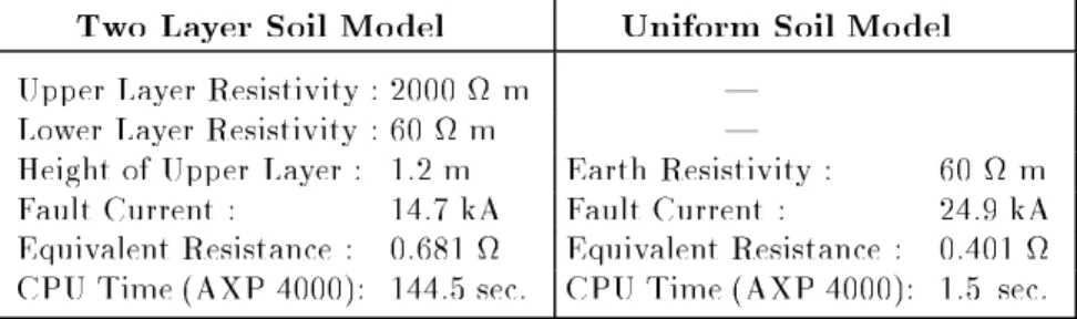
In this pap er, we present the analysis of the Balaidos I I
sub-station grounding (close to the city of Vigo in Spain), by using a
uniform soil mo del and a two layer one. The earthing system
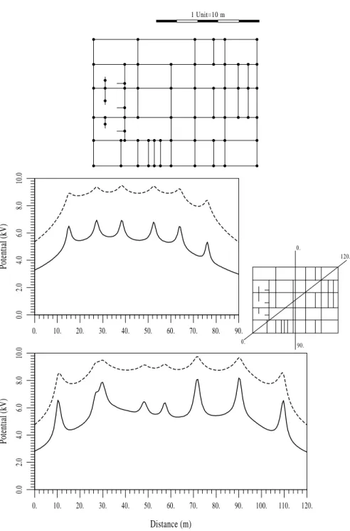
(g-ure 1) is formed by a grid of 107 cylindrical conductors (diameter:
11.28mm)buriedtoadepthof80cm,supplemented with67vertical
ro ds(eachonehasalengthof2.5mandadiameterof14.0mm). The
GroundPotentialRise considered hasb een 10kV.Characteristicsof
thesoil mo delsarepresentedin tableI.Thenumericalmo delusedin
and p otential proles on the earth surface along two dierent lines
obtained with the BEM approach by using uniform and two layer
soil mo dels can b e found in table I and gure 1. As it is shown,
results noticeably vary when dierent soil mo dels are used, and in
consequence thegroundingdesignparameters(equivalent resistance,
thetouch,stepandmeshvoltages,etc.) maysignicantlychange. For
this reason, it will b e essential to p erform the analysis of a system
with this BEM technique although the computing cost increases, in
cases where conductivity changes markedly with depth, in order to
assurethesafetyof theinstallation.
It is imp ortant to notice that,in this case, the grounding
anal-ysis in the two layer soil mo del is very complicated b ecause part of
thegrid is buried in theupp er layer and other in the lower.
There-fore, implementation of the numerical approach must b e carefully
p erformed, in order to consider the dierent arrangements of
elec-tro desinthesoil. Furthermore,since conductivitesoflayersarevery
dierent (=00:94), theanalysis requires an imp ortant computing
eort.
TableI.| BalaidosI ISubstation: Resultsbyusingdierentsoilmo dels
TwoLayer SoilMo del UniformSoilMo del
Upp erLayerResistivity:2000m |
Lower LayerResistivity:60m |
HeightofUpp er Layer: 1.2m EarthResistivity: 60 m
FaultCurrent: 14.7kA FaultCurrent: 24.9kA
EquivalentResistance: 0.681 EquivalentResistance : 0.401
CPUTime(AXP4000): 144.5sec. CPUTime(AXP4000): 1.5 sec.
6 Conclusions
A numerical approach based on the BEM for the analysis of
substationearthingsystems emb edded in layered soils hasb een
pre-sented. This formulation hasb een applied tothe practicalcase of a
groundedsysteminanequivalenttwolayersoil. Takingintoaccount
thereal geometry of these systems, thegeneral 2D approach can b e
rewrittenin terms of an approximated 1D version. Moreover, since
suitablearrangementscanb edoneinthediscretizedexpressions,itis
p ossible to usethesameanalytical integrationtechniques develop ed
by the authors forgrounding analysis in uniform soils. Finally, the
BEMformulationprop osed isa general metho dology that allows to
Thiswork has b een partially supp orted bythe p owercompany
\Union Fenosa", byresearch fellowships of theR&D General
Secre-taryofthe\Xuntade Galicia"andtheUniversityofLaCoru ~na,and
by thecompany\Fecsa".
References
[1] Sverak J.G.,Dick W.K.,Do dds T.H.,Hepp e R.H., Safe
Substa-tionsGrounding,IEEETPAS,100,4281{4290,1981
[2] ANSI/IEEEStd.80,Guide forSafetyinACSubstation
Ground-ing,IEEE Inc., New York,1986
[3] GarretD.L.,PruittJ.G.,ProblemsEncounteredwiththeAPMof
AnalyzingGroundingSystems,IEEETPAS,104,4006{4023,1985
[4] NavarrinaF.,ColominasI.,CasteleiroM.,AnalyticalIntegration
TechniquesforEarthingGridComputationbyBEM,Num. Met.
in Eng. and Appl. Sci.,1197{1206,CIMNE, Barcelona,1992
[5] Colominas I., Navarrina F., Casteleiro M., Una Formulacion
Numerica Generalparael Calculo yDise ~nodeTomasdeTierra
enGrandesInstalacionesElectricas,Rev. Int. Met. Num. Calc.
yDis. Ing., 13, 383{401,1997
[6] DurandE.,
Electrostatique,MassonEd.,Paris,1966
[7] ColominasI.,Cal. yDis. porOrdenadordeTomasdeTierraen
InstalacionesElectricas: Una Formulacion Num. basada en el
MetodoIntegralde Elementosde Contorno,Ph.D.Thesis,
ETS-ICCP,ULC,1995
[8] Aneiros J.M., Una Formulacion Num. para Calc. y Dis. de
TomasdeTierradeSubestacionesElec. conModelosdeTerreno
de2 Capas,ResearchRep ort, ETSICCP,1996
[9] Colominas I., Navarrina F., Casteleiro M., Aneiros J., A BEM
Formulation for CAD of GroundingSystems in Stratied Soils,
IVWorldCong. onComputational Mech., Buenos Aires, 1998
[10] ColominasI.,NavarrinaF.,CasteleiroM.,A BoundaryElement
Formulation for the Substation Grounding Design, Advances in
Engineering Software,Elsevier, [inpress]
[11] CasteleiroM.,HernandezL.A.,ColominasI.,NavarrinaF.,User
Guideof system\TOTBEM" forthe AnalysisandCADof
1 Unit=10 m
0.
10.
20.
30.
40.
50.
60.
70.
80.
90.
0.0
2.0
4.0
6.0
8.0
10.0
Potential (kV)
0.
120.
0.
90.
0.
10.
20.
30.
40.
50.
60.
70.
80.
90.
100.
110.
120.
Distance (m)
0.0
2.0
4.0
6.0
8.0
10.0
Potential (kV)
Fig. 1.|E.R. BaladosI I : Plan of the Grounding(verticalro ds
markedwith black p oints), and Potential proles alongtwo
dier-ent lines (in discontinuous line: results of the uniform mo del; in