DIPLOMADO DE PROFUNDIZACIÓN CISCO PRUEBA DE HABILIDADES PRÁCTICAS CCNP
WILLMAN FABIÁN CELIS CASTELLANOS
UNIVERSIDAD NACIONAL ABIERTA Y A DISTANCIA – UNAD ESCUELA DE CIENCIAS BÁSICAS, TECNOLOGÍA E INGENIERÍA -ECBTI
INGENIERÍA DE TELECOMUNICACIONES PUERTO GAITÁN, META
DIPLOMADO DE PROFUNDIZACIÓN CISCO PRUEBA DE HABILIDADES PRÁCTICAS CCNP
WILLMAN FABIÁN CELIS CASTELLANOS
Diplomado de opción de grado presentado para optar el título de INGENIERO DE TELECOMUNICACIONES
DIRECTOR:
MSc. GERARDO GRANADOS ACUÑA
UNIVERSIDAD NACIONAL ABIERTA Y A DISTANCIA – UNAD ESCUELA DE CIENCIAS BÁSICAS, TECNOLOGÍA E INGENIERÍA -ECBTI
INGENIERÍA DE TELECOMUNICACIONES PUERTO GAITÁN, META
NOTA DE ACEPTACIÓN _______________________ _______________________ _______________________ _______________________ _______________________ _______________________ _______________________
_______________________ Firma del Presidente del Jurado
_______________________ Firma del Jurado
AGRADECIMIENTOS
A mi madre por el apoyo incondicional y moral para realizar y concluir el presente informe, a mi esposa e hija que han sido de inspiración para culminar los objetivos propuestos, al docente Gerardo Granados por las enseñanzas y acompañamiento brindado a lo largo del presente informe, a ellos mi más profunda gratitud.
TABLA DE CONTENIDO
AGRADECIMIENTOS ...4
TABLA DE CONTENIDO ...5
LISTA DE FIGURAS ...6
GLOSARIO ...9
RESUMEN... 10
ABSTRACT... 10
INTRODUCCIÓN ... 11
Descripción de escenarios propuestos para la prueba de habilidades ... 12
Escenario 1: ... 12
Escenario 2: ... 31
CONCLUSIONES ... 57
LISTA DE FIGURAS
Figura 1. Topología de Red – Escenario 1---12
Figura 2. Pantallazo configuración Router R1---13
Figura 3. Pantallazo configuración Router R2---14
Figura 4. Pantallazo configuración Router R3---15
Figura 5. Pantallazo conf. clock rate Router R1 ---16
Figura 6. Pantallazo conf. clock rate Router R2 ---17
Figura 7. Pantallazo conf. clock rate Router R3 ---17
Figura 8. Pantallazo configuración OSPF Router R2---18
Figura 9. Pantallazo configuración OSPF Router R3---18
Figura 10. Pantallazo conf. int. g0/0 OSPF Router R2---19
Figura 11. Pantallazo conf. int. g0/0 OSPF Router R3---20
Figura 12. Pantallazo conf. Área Stubby Router R2---21
Figura 13. Pantallazo conf. Ipv6 OSPF Router R3---22
Figura 14. Pantallazo EIGRP Router R1---23
Figura 15. Pantallazo EIGRP Pasivas Router R1 ---24
Figura 16. Pantallazo EIGRP Pasivas Router R2 ---24
Figura 17. Pantallazo EIGRP Pasivas Router R3 ---24
Figura 18. Pantallazo conf. Redistribución OSPF EIGRP Router R2 ---25
Figura 19. Pantallazo conf. ACL Router R2---25
Figura 20. Pantallazo Tabla Enrutamiento Router R1---26
Figura 21. Pantallazo Tabla Enrutamiento Router R2---27
Figura 22. Pantallazo Tabla Enrutamiento Router R3---27
Figura 23. Pantallazo Verificación Ping1 Router R1---28
Figura 25. Pantallazo Verificación Traceroute Router R1---29
Figura 26. Pantallazo Verificación Rutas Filtradas Router R2 ---30
Figura 27. Topología de Red – Escenario 2 ---31
Figura 28. Pantallazo shutdown Switch DLS1---32
Figura 29. Pantallazo shutdown Switch DLS2---32
Figura 30. Pantallazo shutdown Switch ALS1---33
Figura 31. Pantallazo shutdown Switch ALS2---33
Figura 32. Pantallazo configuración1 Switch DLS1---34
Figura 33. Pantallazo configuración2 Switch DLS1---35
Figura 34. Pantallazo configuración1 Switch DLS2---36
Figura 35. Pantallazo configuración2 Switch DLS2---37
Figura 36. Pantallazo configuración1 Switch ALS1---38
Figura 37. Pantallazo configuración2 Switch ALS1---38
Figura 38. Pantallazo configuración Switch ALS2 ---39
Figura 39. Pantallazo configuración Dominio Switch DLS1---40
Figura 40. Pantallazo configuración Dominio Switch ALS1---41
Figura 41. Pantallazo configuración Dominio Switch ALS2---41
Figura 42. Pantallazo configuración1 VLANs Switch DLS1---42
Figura 43. Pantallazo configuración2 VLANs Switch DLS1---43
Figura 44. Pantallazo suspensión VLAN Switch DLS1---43
Figura 45. Pantallazo configuración1 VLANs Switch DLS2---44
Figura 46. Pantallazo configuración2 VLANs Switch DLS2---45
Figura 47. Pantallazo suspensión VLAN Switch DLS2---45
Figura 48. Pantallazo creación VLAN Switch DLS2---46
Figura 49. Pantallazo conf. Spanning Tree VLANs Switch DLS1---46
Figura 50. Pantallazo conf. Spanning Tree VLANs Switch DLS2---47
Figura 51. Pantallazo conf. Switchport Trunk VLANs Switch DLS1---47
Figura 52. Pantallazo conf. Switchport Trunk VLANs Switch DLS2---48
Figura 54. Pantallazo config2 Switchport access VLANs Switch DLS1---48
Figura 55. Pantallazo config1 Switchport access VLANs Switch DLS2---49
Figura 56. Pantallazo config2 Switchport access VLANs Switch DLS2---49
Figura 57. Pantallazo config. Switchport access VLANs Switch ALS1---50
Figura 58. Pantallazo config. Switchport access VLANs Switch ALS2---51
Figura 59. Pantallazo Verificación VLANs Switch DLS1---52
Figura 60. Pantallazo Verificación VLANs Switch DLS2---52
Figura 61. Pantallazo Verificación VLANs Switch ALS1---53
Figura 62. Pantallazo Verificación VLANs Switch ALS2---53
Figura 63. Pantallazo Verificación Ethernet Switch ALS1---54
Figura 64. Pantallazo Verificación Ethernet Switch ALS2---54
Figura 65. Pantallazo Verificación1 Spanning Tree DLS1---55
Figura 66. Pantallazo Verificación2 Spanning Tree DLS1---55
Figura 67. Pantallazo Verificación1 Spanning Tree DLS2---56
GLOSARIO
RED: Es un conjunto de equipos informáticos y software conectados entre sí por medio de dispositivos físicos o inalámbricos que envían y reciben impulsos eléctricos, ondas electromagnéticas o cualquier otro medio para el transporte de datos, con la finalidad de compartir información, recursos y ofrecer servicios.
CCNP: Es el nivel intermedio de certificación de la compañía CISCO. Para obtener esta certificación, se han de superar varios exámenes, clasificados según la empresa en 3 módulos.
Enrutamiento (Route) Conmutación (Switch)
Resolución de Problemas (Tshoot)
ROUTER: Es un dispositivo que proporciona conectividad a nivel de red o nivel tres en el modelo OSI. Su función principal consiste en enviar o encaminar paquetes de datos de una red a otra, es decir, interconectar subredes.
SWTCH: Es el dispositivo digital lógico de interconexión de equipos que opera en la capa de enlace de datos del modelo OSI. Su función es interconectar dos o más host de manera similar a los puentes de red, pasando datos de un segmento a otro de acuerdo con la dirección MAC de destino de las tramas en la red y eliminando la conexión una vez finalizada ésta.
PROTOCOLO: Es un sistema de reglas que permiten que dos o más entidades de un sistema de comunicación se comuniquen entre ellas para transmitir información por medio de cualquier tipo de variación de una magnitud física.
OSPF: Es un protocolo de red para encaminamiento jerárquico de pasarela interior o Interior Gateway Protocol (IGP), que usa el algoritmo Dijkstra, para calcular la ruta más corta entre dos nodos.
EIGRP: Es un protocolo de encaminamiento de vector distancia, propiedad de Cisco Systems, que ofrece lo mejor de los algoritmos de vector de distancia. Se considera un protocolo avanzado que se basa en las características normalmente asociadas con los protocolos del estado de enlace.
RESUMEN
Este proyecto consiste en el proceso de conceptualización de los diversos temas del área de networking y seguridad, donde se profundizó en uso y beneficios de las VLANs, protocolos de enrutamiento como EIRP, OSPF, entre otros. De la misma forma, la aplicación práctica de los mismos sobre diversos esquemas topológicos de red para los módulos de CCNP ROUTE y SWITCH en ambientes de simulación lógica.
El objetivo principal es el enriquecimiento del estudiante en un área de profundización del área de telecomunicaciones que permita poseer una base práctica para el mejoramiento del pensamiento crítico y la capacidad de análisis proactivo sobre plataforma de red, el análisis de situaciones conflictivas que permitan al estudiante entender el funcionamiento de corta, mediana y gran envergadura.
Palabras clave: CISCO, CCNP, Redes, Router, Switch.
ABSTRACT
This project consists of the conceptualization process of the various topics in the area of networks and security, where the use and benefits of VLANs, routing protocols such as EIRP, OSPF, among others, are explored. In the same way, the practical application of the same on diverse network topological schemes for the CCNP ROUTE and SWITCH modules in logical simulation environments.
The main objective is the enrichment of the student in a deepening area of the telecommunications area that can have a practical basis for the improvement of critical thinking and the ability of proactive analysis on the network platform, the analysis of conflict situations that could at student understand the operation of short, medium and large wingspan.
INTRODUCCIÓN
Durante la realización del Diplomado de Profundización CCNP de CISCO se fortalecen las habilidades en networking y se adquiere conocimiento necesario que permita a futuros profesionales desempeñarse de manera satisfactoria en redes WAN, protocolos de enrutamiento, implementación de soluciones soportadas en enrutamiento avanzado, VLANs, entre otros.
En el siguiente documento se desarrollarán dos prácticas correspondientes a dos escenarios, uno que tiene que ver con el módulo CCNP ROUTE, y el otro con el módulo CCNP SWITCH. En el desarrollo de estos dos escenarios se identificará el grado de competencias y habilidades adquiridas a lo largo del curso. Estos escenarios se desarrollarán en el software Packet Tracer.
En el escenario 1 de CCNP ROUTE se abordarán temas como protocolos de enrutamiento EIGRP y OSPF. En el escenario 2 de CCNP SWITCH se abordarán temas como VLANs, Spanning-Tree, operaciones y puertos de switches.
Descripción de escenarios propuestos para la prueba de habilidades
Escenario 1:
Una empresa de confecciones posee tres sucursales distribuidas en las ciudades de Bogotá, Medellín y Bucaramanga, en donde el estudiante será el administrador de la red, el cual deberá configurar e interconectar entre sí cada uno de los dispositivos que forman parte del escenario, acorde con los lineamientos establecidos para el direccionamiento IP, protocolos de enrutamiento y demás aspectos que forman parte de la topología de red.
Topología de Red
|
Figura 1. Topología de Red – Escenario 1
Configurar la topología de red, de acuerdo con las siguientes especificaciones: Parte 1: Configuración del escenario propuesto
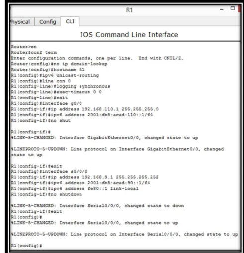
1. Configurar las interfaces con las direcciones IPv4 e IPv6 que se muestran en la topología de red.
Router R1
hostname R1 ipv6 unicast-routing line con 0
logging synchronous exec-timeout 0 0 exit
interface g0/0
ip address 192.168.110.1 255.255.255.0 ipv6 address 2001:db8:acad:110::1/64 no shutdown
exit
interface s0/0/0
ip address 192.168.9.1 255.255.255.252 ipv6 address 2001:db8:acad:90::1/64 ipv6 address fe80::1 link-local
no shutdown exit
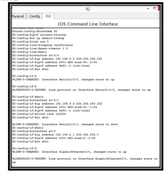
Router R2
Figura 3. Pantallazo configuración Router R2
no ip domain-lookup hostname R2
ipv6 unicast-routing line con 0
logging synchronous exec-timeout 0 0 exit
interface s0/0/0
ip address 192.168.9.2 255.255.255.252 ipv6 address 2001:db8:acad:90::2/64 ipv6 address fe80::2 link-local
no shutdown exit
ip address 192.168.9.5 255.255.255.252 ipv6 address 2001:db8:acad:91::1/64 ipv6 address fe80::2 link-local
clock rate 128000 no shutdown exit
interface g0/0
ip address 192.168.2.1 255.255.255.0 ipv6 address 2001:db8:acad:b::1/64 no shutdown
exit
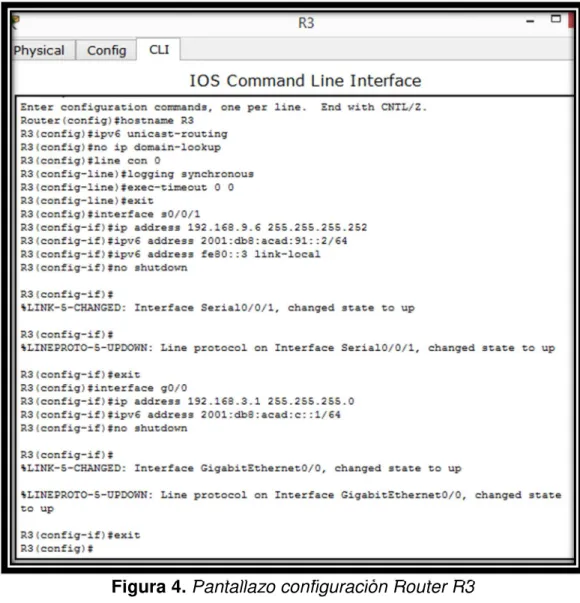
Router R3
hostname R3 ipv6 unicast-routing no ip domain-lookup line con 0
logging synchronous exec-timeout 0 0 exit
interface s0/0/1
ip address 192.168.9.6 255.255.255.252 ipv6 address 2001:db8:acad:91::2/64 ipv6 address fe80::3 link-local
no shutdown exit
interface g0/0
ip address 192.168.3.1 255.255.255.0 ipv6 address 2001:db8:acad:c::1/64 no shutdown
exit
2. Ajustar el ancho de banda a 128 kbps sobre cada uno de los enlaces seriales ubicados en R1, R2, y R3 y ajustar la velocidad del reloj de las conexiones DCE según sea apropiado.
Router R1
int s0/0/0 bandwidth 128 clock rate 128000 no shutdown
Router R2
Figura 6. Pantallazo conf. clock rate Router R2
int s0/0/0 bandwidth 128 no shutdown exit
int s0/0/1 bandwidth 128 clock rate 128000 no shutdown exit
Router R3
int s0/0/1 bandwidth 128 no shutdown exit
3. En R2 y R3 configurar las familias de direcciones OSPFv3 para IPv4 e IPv6. Utilice el identificador de enrutamiento 2.2.2.2 en R2 y 3.3.3.3 en R3 para ambas familias de direcciones.
En vista que OSPFv3 es equivalente a OSPFv2 en el intercambio de prefijos IPv6, ya que en este caso la dirección de red se denomina prefijo, y la máscara de subred, longitud de prefijo.
Router R2 router ospf 1
log-adjacency-changes router-id 2.2.2.2
network 192.168.2.0 0.0.0.255 area 1 network 192.168.9.4 0.0.0.3 area 0 exit
Figura 8. Pantallazo configuración OSPF Router R2 Router R3
router ospf 1
log-adjacency-changes router-id 3.3.3.3
network 192.168.3.0 0.0.0.255 area 0 network 192.168.9.4 0.0.0.3 area 0 exit
4. En R2, configurar la interfaz G0/0 en el área 1 de OSPF y la conexión serial entre R2 y R3 en OSPF área 0.
Router R2
int g0/0
ip ospf 1 area 1 exit
int s0/0/1
ip ospf 1 area 0 exit
5. En R3, configurar la interfaz G0/0 y la conexión serial entre R2 y R3 en OSPF área 0.
Router R3
int g0/0
ip ospf 1 area 0 exit
int s0/0/1
ip ospf 1 area 0 exit
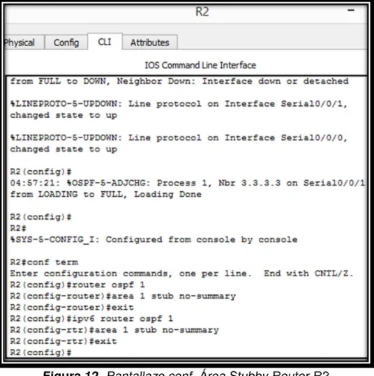
6. Configurar el área 1 como un área totalmente Stubby.
Esta área es propietaria de Cisco, esto quiere decir que no acepta rutas de otros tipos de sistemas externos o rutas sumarizadas desde otras áreas internas. Al igual que en las áreas Stub, los routers se encargan de enviar una ruta por defecto para todas las rutas externas y sumarizadas.
Router R2
router ospf 1
area 1 stub no-summary exit
ipv6 router ospf 1
área 1 stub no-summary exit
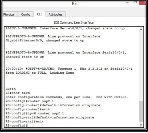
7. Propagar rutas por defecto de IPv4 e IPv6 en R3 al interior del dominio OSPFv3. Nota: Es importante tener en cuenta que una ruta por defecto es diferente a la definición de rutas estáticas.
Router R3
router ospf 1
default-information originate exit
ipv6 router ospf 1
default-information originate exit
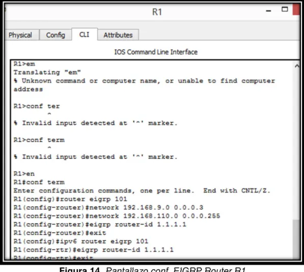
8. Realizar la configuración del protocolo EIGRP para IPv4 como IPv6. Configurar la interfaz G0/0 de R1 y la conexión entre R1 y R2 para EIGRP con el sistema autónomo 101. Asegúrese de que el resumen automático está desactivado.
Router R1
router eigrp 101
network 192.168.9.0 0.0.0.3 network 192.168.110.0 0.0.0.255 eigrp router-id 1.1.1.1
exit
ipv6 router eigrp 101 eigrp router-id 1.1.1.1 exit
9. Configurar las interfaces pasivas para EIGRP según sea apropiado.
Router R1
ipv6 router eigrp 101 passive-interface g0/0 exit
Figura 15. Pantallazo conf. EIGRP Pasivas Router R1
Router R2
ipv6 router eigrp 101 passive-interface g0/0 exit
Figura 16. Pantallazo conf. EIGRP Pasivas Router R2
Router R3
ipv6 router eigrp 101 passive-interface g0/0 exit
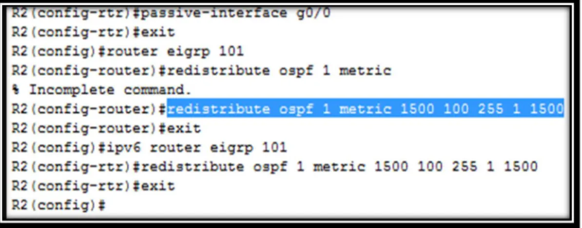
10. En R2, configurar la redistribución mutua entre OSPF y EIGRP para IPv4 e IPv6. Asignar métricas apropiadas cuando sea necesario.
Router R2
router eigrp 101
redistribute ospf 1 metric 1500 100 255 1 1500 exit
ipv6 router eigrp 101
redistribute ospf 1 metric 1500 100 255 1 1500 exit
Figura 18. Pantallazo conf. Redistribución OSPF EIGRP Router R2
11. En R2, de hacer publicidad de la ruta 192.168.3.0/24 a R1 mediante una lista de distribución y ACL.
Router R2
access-list 1 deny 192.168.3.0 0.0.0.255 access-list 1 permit any
Parte 2: Verificar conectividad de red y control de la trayectoria.
a. Registrar las tablas de enrutamiento en cada uno de los routers, acorde con los parámetros de configuración establecidos en el escenario propuesto.
Router R1
Router R2
Figura 21. Pantallazo Tabla Enrutamiento Router R2 Router R3
b. Verificar comunicación entre routers mediante el comando ping y traceroute
Router R1
Figura 24. Pantallazo Verificación Ping2 Router R1
c. Verificar que las rutas filtradas no están presentes en las tablas de enrutamiento de los routers correctas.
Router R2
show access-lists
Figura 26. Pantallazo Verificación Rutas Filtradas Router R2
Escenario 2:
Una empresa de comunicaciones presenta una estructura Core acorde a la topología de red, en donde el estudiante será el administrador de la red, el cual deberá configurar e interconectar entre sí cada uno de los dispositivos que forman parte del escenario, acorde con los lineamientos establecidos para el direccionamiento IP, etherchannels, VLANs y demás aspectos que forman parte del escenario propuesto.
Topología de Red
Figura 27. Topología de Red – Escenario 2
Parte 1: Configurar la red de acuerdo con las especificaciones.
a. Apagar todas las interfaces en cada switch
Switch DLS1
hostname DLS1
int range f0/1-24, g0/1-2 shutdown
Figura 28. Pantallazo shutdown Switch DLS1
Switch DLS2
hostname DLS2
int range f0/1-24, g0/1-2 shutdown
exit
Switch ALS1
hostname ALS1
int range f0/1-24, g0/1-2 shutdown
exit
Figura 30. Pantallazo shutdown Switch ALS1
Switch ALS2
hostname ALS2
int range f0/1-24, g0/1-2 shutdown
exit
b. Asignar un nombre a cada switch acorde al escenario establecido.
En la configuración anterior se estableció el nombre a cada switch
c. Configurar los puertos troncales y Port-channels tal como se muestra en el diagrama.
1. La conexión entre DLS1 y DLS2 será un EtherChannel capa-3 utilizando LACP. Para DLS1 se utilizará la dirección IP 10.12.12.1/30 y para DLS2 utilizará 10.12.12.2/30.
2. Los Port-channels en las interfaces Fa0/7 y Fa0/8 utilizarán LACP. 3. Los Port-channels en las interfaces F0/9 y fa0/10 utilizará PAgP.
4. Todos los puertos troncales serán asignados a la VLAN 800 como la VLAN nativa.
Switch DLS1
int range f0/11-12 no switchport
channel-group 12 mode active no shutdown
interface port-channel 12
ip address 10.12.12.1 255.255.255.252 exit
int range f0/7-10
switchport trunk encapsulation dot1q switchport trunk native vlan 800 switchport mode trunk
switchport nonegotiate no shutdown
exit
int range f0/7-8
desc member of po1 to ALS1 channel-group 1 mode active exit
int range f0/9-10
desc member of po4 to ALS2 channel-group 4 mode desirable exit
Switch DLS2
int range f0/11-12 no switchport
channel-group 12 mode active no shutdown
interface port-channel 12
ip address 10.12.12.2 255.255.255.252
Figura 34. Pantallazo configuración1 Switch DLS2
int range f0/7-10
switchport trunk encapsulation dot1q switchport trunk native vlan 800 switchport mode trunk
switchport nonegotiate no shutdown
exit
int range f0/7-8
int range f0/9-10
desc member of po3 to ALS1 channel-group 3 mode desirable exit
Figura 35. Pantallazo configuración2 Switch DLS2
Switch ALS1
int range f0/7-10
switchport trunk native vlan 800 switchport mode trunk
switchport nonegotiate no shutdown
exit
int range f0/7-8
desc member of po1 to DLS1 channel-group 1 mode active no shutdown
Figura 36. Pantallazo configuración1 Switch ALS1
int range f0/9-10
desc member of po 3 to DLS2 channel-group 3 mode desirable no shutdown
exit
Switch ALS2
int range f0/7-10
switchport trunk native vlan 800 switchport mode trunk
switchport nonegotiate exit
int range f0/7-8
desc member of po2 to DLS2 channel-group 2 mode active no shutdown
exit
int range f0/9-10
desc member of po 4 to DLS1 channel-group 4 mode desirable no shutdown
exit
d. Configurar DLS1, ALS1, y ALS2 para utilizar VTP versión 3
1. Utilizar el nombre de dominio UNAD con la contraseña cisco123 2. Configurar DLS1 como servidor principal para las VLAN
3. Configurar ALS1 y ALS2 como clientes VTP Switch DLS1
vtp domain UNAD vtp version 2
vtp password cisco123 vtp primary vlan
Figura 39. Pantallazo configuración Dominio Switch DLS1
Switch ALS1 vtp domain UNAD vtp version 2 vtp mode client
Figura 40. Pantallazo configuración Dominio Switch ALS1
Switch ALS2 vtp domain UNAD vtp version 2 vtp mode client
vtp password cisco123
e. Configurar en el servidor principal las siguientes VLAN:
vlan 800 name NATIVA exit
vlan 434
name ESTACIONAMIENTO exit
vlan 12
name EJECUTIVOS exit
Figura 42. Pantallazo configuración1 VLANs Switch DLS1
vlan 123
name MANTENIMIENTO exit
vlan 234
name HUESPEDES exit
vlan 101 name VOZ exit
name VIDEONET exit
vlan 345
name ADMINISTRACION
Figura 43. Pantallazo configuración2 VLANs Switch DLS1
f. En DSL1 suspender la VLAN 434.
vlan 434 state suspend exit
g. Configurar DLS2 en modo VTP transparente VTP utilizando VTP versión 2, y configurar en DLS2 las mismas VLAN que en DLS1
Switch DLS2
vtp version 2
vtp mode transparent vlan 800 name NATIVA exit vlan 434 name ESTACIONAMIENTO exit vlan 12 name EJECUTIVOS exit vlan 123 name MANTENIMIENTO exit vlan 234 name HUESPEDES exit vlan 101 name VOZ exit
vlan 111
name VIDEONET exit
vlan 345
name ADMINISTRACION
Figura 46. Pantallazo configuración2 VLANs Switch DLS2
h. Suspender VLAN 434 en DLS2
Switch DLS2
vlan 434 state suspend exit
i. En DLS2, crear VLAN 567 con el nombre de CONTABILIDAD. La VLAN de CONTABILIDAD no podrá estar disponible en cualquier otro Switch de la red.
Switch DLS2
vlan 567
name CONTABILIDAD exit
Figura 48. Pantallazo creación VLAN Switch DLS2
j. Configurar DLS1 como Spanning tree root para las VLAN 1, 12, 434, 800, 101, 111 y 345 y como raíz secundaria para las VLAN 123 y 234.
Switch DLS1
spanning-tree vlan 1,12,434,800,101,111,345 root primary spanning-tree vlan 123,234 root secondary
Figura 49. Pantallazo conf. Spanning tree VLANs Switch DLS1
k. Configurar DLS2 como Spanning tree root para las VLAN 123 y 234 y como una raíz secundaria para las VLAN 1, 12, 434, 800, 101, 111 y 345.
Switch DLS2
spanning-tree vlan 123,234 root primary
Figura 50. Pantallazo conf. Spanning tree VLANs Switch DLS2
l. Configurar todos los puertos como troncales de tal forma que solamente las VLAN que se han creado se les permitirá circular a través de éstos puertos.
Switch DLS1
int port-channel 1
switchport trunk allowed vlan 12,123,234,800,101,111,345 exit
int port-channel 4
switchport trunk allowed vlan 12,123,234,800,101,111,345
Figura 51. Pantallazo conf. Switchport trunk VLANs Switch DLS1
Switch DLS2
int port-channel 2
switchport trunk allowed vlan 12,123,234,800,101,111,345 int port-channel 3
Figura 52. Pantallazo conf. Switchport trunk VLANs Switch DLS2
m. Configurar las siguientes interfaces como puertos de acceso, asignados a las VLAN de la siguiente manera:
Switch DLS1 int f0/6
switchport host
switchport access vlan 345 no shutdown
exit int f0/15
switchport host
switchport access vlan 111 no shutdown
exit
Figura 53. Pantallazo config1 Switchport access VLANs Switch DLS1
Switch DLS2 int f0/6
switchport host
switchport access vlan 12 switchport voice vlan 101 no shutdown
exit int f0/15
switchport host
switchport access vlan 111 no shutdown
exit
int range f0/16-18 switchport host
switchport access vlan 567 no shutdown
Figura 55. Pantallazo config1 Switchport access VLANs Switch DLS2
Switch ALS1
int f0/6
switchport host
switchport access vlan 123 switchport voice vlan 101 no shutdown
exit int f0/15
switchport host
switchport access vlan 111 no shutdown
exit
Figura 57. Pantallazo config. Switchport access VLANs Switch ALS1
Switch ASL2
int f0/6
switchport host
exit int f0/15
switchport host
switchport access vlan 111 no shutdown
exit
Parte 2: Conectividad de red de prueba y las opciones configuradas
a. Verificar la existencia de las VLAN correctas en todos los switches y la asignación de puertos troncales y de acceso
Switch DLS1
Figura 59. Pantallazo Verificación VLANs Switch DLS1
Switch DLS2
Switch ALS1
Figura 61. Pantallazo Verificación VLANs Switch ALS1
Switch ALS2
Figura 62. Pantallazo Verificación VLANs Switch ALS2
Switch DLS1
Figura 63. Pantallazo Verificación Ethernet Switch DLS1
Switch ALS2
Figura 64. Pantallazo Verificación Ethernet Switch ALS2
Switch DLS1
Figura 65. Pantallazo Verificación1 Spanning Tree Switch DLS1
Switch DLS2
Figura 67. Pantallazo Verificación1 Spanning Tree Switch DLS2
CONCLUSIONES
El uso de protocolos de enrutamiento dinámico permite el aprendizaje de la topología de red que se esté trabajando y la cantidad de saltos posibles para alcanzar una destino.
Se debe tener cuidado al momento de implementar un esquema de red usando el protocolo VTP ya que al ser el aprendizaje de Vlan dinámico, la introducción de un nuevo Switch con un número de revisión más alto puede afectar el funcionamiento y generar indisponibilidad.
Como elemento de seguridad el uso de Vlan permite la segmentación adecuada de una red limitando el acceso a los recursos que sean absolutamente necesarios y logrando una división basada en departamentos, servicios o localidades.
REFERENCIAS BIBLIOGRÁFICAS
- Configuración DHCP en Router (s.f), 27 de Mayo de 2018. Recuperado de https://apuntesdecisco.blogspot.com/2008/07/configuracin-de-dhcp-en-elrouter.html.
- Froom, R., Frahim, E. (2015). CISCO Press (Ed). Spanning Tree Implementation. Implementing Cisco IP Switched Networks (SWITCH) Foundation Learning Guide CCNP SWITCH 300-115. Recuperado de https://1drv.ms/b/s!AmIJYeiNT1IlnWR0hoMxgBNv1CJ
- Guía de diseño de OSPF. CISCO. Recuperado de https://www.cisco.com/c/es_mx/support/docs/ip/open-shortest-path-first-ospf/7039-1.htm
- Teare, D., Vachon B., Graziani, R. (2015). CISCO Press (Ed). Basic Network and Routing Concepts. Implementing Cisco IP Routing (ROUTE) Foundation Learning Guide CCNP ROUTE 300-101. Recuperado de https://1drv.ms/b/s!AmIJYei-NT1IlnMfy2rhPZHwEoWx
- UNAD (2015). Introducción a la configuración de Switches y Routers [OVA]. Recuperado de https://1drv.ms/u/s!AmIJYei-NT1IhgL9QChD1m9EuGqC
- UNAD (2015). Switch CISCO - Procedimientos de instalación y configuración del IOS [OVA]. Recuperado de https://1drv.ms/u/s!AmIJYei-NT1IlyYRohwtwPUV64dg