DIPLOMADO DE PROFUNDIZACION CISCO PRUEBA DE HABILIDADES PRACTICAS CCNP
JOSE LUIS NIÑO MANCIPE
UNIVERSIDAD NACIONAL ABIERTA Y A DISTANCIA - UNAD
ESCUELA DE CIENCIAS BÁSICAS, TECNOLOGÍA E INGENIERÍA - ECBTI INGENIERÍA ELECTRONICA
DIPLOMADO DE PROFUNDIZACION CISCO PRUEBA DE HABILIDADES PRÁCTICAS CCNP
JOSE LUIS NIÑO MANCIPE
Diplomado de opción de grado presentado para optar el título de INGENIERO ELECTRONICO
DIRECTOR:
MSc. GERARDO GRANADOS ACUÑA
UNIVERSIDAD NACIONAL ABIERTA Y A DISTANCIA - UNAD
ESCUELA DE CIENCIAS BÁSICAS, TECNOLOGÍA E INGENIERÍA - ECBTI INGENIERÍA ELECTRONICA
3
NOTA DE ACEPTACION
__________________________ __________________________ __________________________ __________________________ __________________________ __________________________ __________________________
__________________________ Firma del presidente del Jurado
__________________________ Firma del jurado
__________________________ Firma del jurado
4
AGRADECIMIENTOS
Dedico esta página a Dios que es mi guía para el desarrollo de todas mis metas y objetivos en la vida, además quiero agradecer a mi familia que son personas incondicionales.
5 CONTENIDO
CONTENIDO ... 5
LISTA DE ILUSTRACIONES ... 6
LISTA DE TABLAS ... 9
GLOSARIO ... 10
RESUMEN ... 12
ABSTRACT ... 12
1. DESARROLLO ... 15
1.1. Prueba de habilidades - Escenario 1 ... 15
1.1.1. Topología de red 1 ... 15
Parte 1: Configuración del escenario propuesto ... 16
Parte 2: Verificar conectividad de red y control de la trayectoria. ... 24
1.1.2. ESCENARIO COMANDOS 1 ... 27
ROUTER 2 ... 29
ROUTER 3 ... 33
1.2. Prueba de Habilidades - Escenario 2 ... 37
1.2.1. Topología de red 2 ... 37
Parte 1: Configurar la red de acuerdo con las especificaciones. ... 38
Parte 2: conectividad de red de prueba y las opciones configuradas. ... 63
1.2.2. ESCENARIO COMANDOS 2 ... 71
DLS1 ... 71
DLS2 ... 74
ALS1 ... 80
ALS2 ... 82
CONCLUSIONES ... 85
6
LISTA DE ILUSTRACIONES
Ilustración 1. Topología de red E1 ... 15
Ilustración 2. Topología de red E1 Software Packet Tracer ... 15
Ilustración 3. R1: Configuración ... 16
Ilustración 4. R2: Configuración ... 16
Ilustración 5. R3: Configuración ... 17
Ilustración 6. R1: Ajuste de banda ... 17
Ilustración 7. R2: Ajuste de banda ... 18
Ilustración 8. R3: Ajuste de banda ... 18
Ilustración 9. R2: Configuración de direcciones OSPFv3 ... 19
Ilustración 10. R2: Configuración de direcciones OSPFv3 ... 19
Ilustración 11. R2: Configuración de la interfaz F0/0 ... 20
Ilustración 12. R3: Configuración de la interfaz F0/0 ... 20
Ilustración 13. R2: Configuración en A1 ... 21
Ilustración 14. R3: Configuración de rutas ... 21
Ilustración 15. R1: configuración del protocolo EIGRP ... 22
Ilustración 16. R1: Configuración de las interfaces EIGRP ... 22
Ilustración 17. R2: Configuración entre OSPF y EIGRP ... 23
Ilustración 18. R2: Publicidad de la ruta ... 23
Ilustración 19. R1: Enrutamiento ... 24
Ilustración 20. R2: Enrutamiento ... 24
Ilustración 21. R2: Enrutamiento ... 25
Ilustración 22.R1: Comprobando comunicación... 25
Ilustración 23. R2: Comprobaciones ... 26
Ilustración 24. Topología de Red E2 ... 37
Ilustración 25. Topología de red E2 Software Packet Tracer ... 37
Ilustración 26. Switch DLS1: Apagando interfaces ... 38
Ilustración 27. Switch DLS2: Apagando interfaces ... 38
Ilustración 28. Switch ALS1: Apagando interfaces ... 39
Ilustración 29. Switch ALS2: Apagando interfaces ... 39
Ilustración 30. Switch DLS1: Establecido un nombre ... 40
Ilustración 31. Switch DLS2: Establecido un nombre ... 40
Ilustración 32. Switch ALS1: Establecido un nombre ... 41
Ilustración 33. Switch ALS2: Establecido un nombre ... 41
Ilustración 34. Switch DLS1: Realizando Conexión ... 42
7
Ilustración 36. Switch DLS1: Configuración de los Port-channels en las interfaces
Fa0/7 y Fa0/8 utilizará LACP ... 43
Ilustración 37. Switch DLS1: Configuración de los Port-channels en las interfaces Fa0/7 y Fa0/8 utilizará LACP ... 43
Ilustración 38. Switch ALS1: Configuración de los Port-channels en las interfaces Fa0/7 y Fa0/8 utilizará LACP ... 44
Ilustración 39. Switch ALS1: Configuración de los Port-channels en las interfaces Fa0/7 y Fa0/8 utilizará LACP ... 44
Ilustración 40. Switch DLS1: Configuración de los Port-channels en las interfaces F0/9 y fa0/10 utilizará PAgP ... 45
Ilustración 41. Switch DLS1: Configuración de los Port-channels en las interfaces F0/9 y fa0/10 utilizará PAgP ... 45
Ilustración 42. Switch ALS1: Configuración de los Port-channels en las interfaces F0/9 y fa0/10 utilizará PAgP ... 46
Ilustración 43. Switch ALS1: Configuración de los Port-channels en las interfaces F0/9 y fa0/10 utilizará PAgP ... 46
Ilustración 44. Switch DLS1: Asignación ... 47
Ilustración 45. Switch DLS1: Asignación ... 47
Ilustración 46. Switch DLS2: Asignación ... 48
Ilustración 47. Switch DLS2: Asignación ... 48
Ilustración 48.Switch DLS2: Asignación ... 49
Ilustración 49. Switch ALS1: Asignación ... 49
Ilustración 50. Switch ALS1: Asignación ... 50
Ilustración 51. Switch ALS2: Asignación ... 50
Ilustración 52. Switch ALS2: Asignación ... 51
Ilustración 53. Switch ALS2: Asignación ... 51
Ilustración 54. Switch DLS1: Configuración de Nombre y dominio ... 52
Ilustración 55. Switch DLS1: Configuración del servidor ... 52
Ilustración 56. Switch ALS1: Configuración ALS1 como clientes VTP. ... 53
Ilustración 57. Switch ALS2: Configuración ALS1 como clientes VTP. ... 53
Ilustración 58. Switch DLS1: Configuración del servidor principal ... 54
Ilustración 59. Switch DLS1: Suspender la VLAN 434 ... 55
Ilustración 60. Switch DLS1: Suspender la VLAN 434 ... 55
Ilustración 61.Switch DLS2: Configuración DLS2 en modo VTP ... 56
Ilustración 62. Switch DLS2: Suspendiendo VLAN ... 56
Ilustración 63. Switch DLS2: Suspendiendo VLAN ... 57
Ilustración 64. Switch DLS2: Se crea el nombre de CONTABILIDAD ... 57
Ilustración 65. Switch DLS1: Configuración como Spanning tree root ... 58
8
Ilustración 67. Switch DLS1: Configuración los puertos ... 59
Ilustración 68. Switch DLS2: Configuración los puertos ... 59
Ilustración 69. Switch ALS1: Configuración los puertos ... 60
Ilustración 70. Switch ALS1: Configuración los puertos ... 60
Ilustración 71. Switch DLS1: Configuración de interfaces ... 61
Ilustración 72. Switch DLS2: Configuración de interfaces ... 62
Ilustración 73. Switch ALS1: Configuración de interfaces ... 62
Ilustración 74.Switch ALS1: Configuración de interfaces ... 63
Ilustración 75. Switch DLS1: Verificación la existencia de las VLAN ... 63
Ilustración 76. Switch DLS2: Verificación la existencia de las VLAN ... 64
Ilustración 77. Switch ALS1: Verificación la existencia de las VLAN ... 64
Ilustración 78. Switch ALS2: Verificación la existencia de las VLAN ... 65
Ilustración 79. Switch DLS1: Verificación ... 65
Ilustración 80. Switch DLS1: Verificación ... 66
Ilustración 81. Switch DLS1: Configuración de Spanning tree ... 66
Ilustración 82. Switch DLS1: Configuración de Spanning tree ... 67
Ilustración 83. Switch DLS2: Configuración de Spanning tree ... 67
Ilustración 84. Switch DLS2: Configuración de Spanning tree ... 68
Ilustración 85. Switch ALS1: Configuración de Spanning tree ... 68
Ilustración 86.Switch ALS1: Configuración de Spanning tree ... 69
Ilustración 87. Switch ALS2: Configuración de Spanning tree ... 69
9
LISTA DE TABLAS
10 GLOSARIO
CISCO CCNP: La Certificación Cisco Certified Network Professional (CCNP) te aprueba la habilidad para planificar, implementar, verificar y resolver problemas de redes locales. De igual forma te permite trabajar en colaboración con especialistas en soluciones avanzadas de seguridad, voz, Wireless y video.
Digitization: Migrar del mundo físico al digital. Esto incluye no solamente documentos y procesos de negocio, sino el negocio en sí: mostrar y vender productos en una tienda en línea, tener el historial de sus clientes en tiempo real, ofrecer servicios en Internet.
EIGRP: es una versión mejorada de IGRP. La tecnología de vector de igual distancia que se usa en IGRP también se emplea en EIGRP. Además, la información de la distancia subyacente no presenta cambios
CONECTIVIDAD: Es la capacidad de establecer una conexión: una comunicación, un vínculo. El concepto suele aludir a la disponibilidad que tiene de un dispositivo para ser conectado a otro o a una red.
IGRP utiliza la tecnología de ruteo del vector de distancia. El concepto es que cada Router no necesita conocer todas las relaciones del Router/del link para toda la red. Cada Router anuncia destinos con una distancia correspondiente. Cada Router que escucha la información ajusta la distancia y la propaga a los Routers vecinos.
SWITCH: El switch es uno de los componentes fundamentales en el desarrollo de Internet. Funciona como lo hacían los conmutadores telefónicos: recibe paquetes de datos y los direcciona al destinatario correcto.
VTP: Se emplea para centralizar en un solo switch la administración de VLANS
VLAN: Red de área local virtual, hace referencia a una red de área local enlazada de manera lógica (no física) Enrutamiento
ACCESS POINT: Es un dispositivo que habilita la conexión inalámbrica. El módem que le ofrece su proveedor de Internet, es un Access Point.
11
SERVER: Un servidor es una computadora con altos niveles de almacenamiento y procesamiento. En él, las organizaciones instalan y ejecutan sistemas y servicios como los de facturación, recursos humanos y aplicaciones de colaboración.
PACKET TRACER: es un software desarrollado por cisco que permite la simulación de redes.
12 RESUMEN
En el presente proyecto encontraremos el desarrollo de dos escenarios planteados para la prueba de habilidades prácticas de diplomado de profundización CISCO CCNP, con el fin y propósito de poner en práctica cada una de las actividades desarrolladas en el curso, y afianzar nuestro conocimiento.
El escenario 1 es una red para una empresa de confecciones que posee tres sucursales distribuidas en las ciudades de Bogotá, Medellín y Bucaramanga, en donde el estudiante será el administrador de la red, el cual deberá configurar e interconectar entre sí cada uno de los dispositivos que forman parte del escenario, acorde con los lineamientos establecidos para el direccionamiento IP, protocolos de enrutamiento y demás aspectos que forman parte de la topología de red.
Y en el escenario 2 es una red para empresa de comunicaciones, presenta una estructura Core acorde a la topología de red, en donde el estudiante será el administrador de la red, el cual deberá configurar e interconectar entre sí cada uno de los dispositivos que forman parte del escenario, acorde con los lineamientos establecidos para el direccionamiento IP, etherchannels, VLANs y demás aspectos que forman parte del escenario propuesto.
PALABRAS CLAVE: Red, CCNP, Vlans, Cisco, conectividad, Switch, Router, enrutamiento, EBGP, VTP, Escenarios, Packet Tracer
ABSTRACT
In this project we will find the development of two scenarios proposed for the practical skills test of the CISCO CCNP deepening diploma, with the purpose and purpose of putting into practice each of the activities developed in the course, and strengthening our knowledge.
Scenario 1 is a network for a clothing company that has three branches distributed in the cities of Bogotá, Medellín and Bucaramanga, where the student will be the administrator of the network, which must configure and interconnect each of the devices that are part of the scenario, according to the established guidelines for IP addressing, routing protocols and other aspects that are part of the network
topology.
And in scenario 2 it is a network for a communications company, it presents a Core structure according to the network topology, where the student will be the
13
IP addressing, etherchannels, VLANs and other aspects that are part of the proposed scenario.
14
INTRODUCCION
En el siguiente documento se encuentran desarrollados los dos escenarios planteados en la guía de habilidades prácticas del curso de profundización CISCO CCNP.
15
1. DESARROLLO 1.1. Prueba de habilidades - Escenario 1
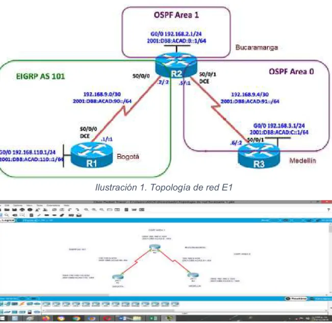
Una empresa de confecciones posee tres sucursales distribuidas en las ciudades de Bogotá, Medellín y Bucaramanga, en donde el estudiante será el administrador de la red, el cual deberá configurar e interconectar entre sí cada uno de los dispositivos que forman parte del escenario, acorde con los lineamientos establecidos para el direccionamiento IP, protocolos de enrutamiento y demás aspectos que forman parte de la topología de red.
1.1.1. Topología de red 1
Ilustración 1. Topología de red E1
16
Configurar la topología de red, de acuerdo con las siguientes especificaciones. Parte 1: Configuración del escenario propuesto
1. Configurar las interfaces con las direcciones IPv4 e IPv6 que se muestran en la topología de red.
Ilustración 3. R1: Configuración
17
Ilustración 5. R3: Configuración
2. Ajustar el ancho de banda a 128 kbps sobre cada uno de los enlaces seriales ubicados en R1, R2, y R3 y ajustar la velocidad de reloj de las conexiones de DCE según sea apropiado.
18
Ilustración 7. R2: Ajuste de banda
19
3. En R2 y R3 configurar las familias de direcciones OSPFv3 para IPv4 e IPv6. Utilice el identificador de enrutamiento 2.2.2.2 en R2 y 3.3.3.3 en R3 para ambas familias de direcciones.
Ilustración 9. R2: Configuración de direcciones OSPFv3
20
4. En R2, configurar la interfaz F0/0 en el área 1 de OSPF y la conexión serial entre R2 y R3 en OSPF área 0.
Ilustración 11. R2: Configuración de la interfaz F0/0
5. En R3, configurar la interfaz F0/0 y la conexión serial entre R2 y R3 en OSPF área 0.
21
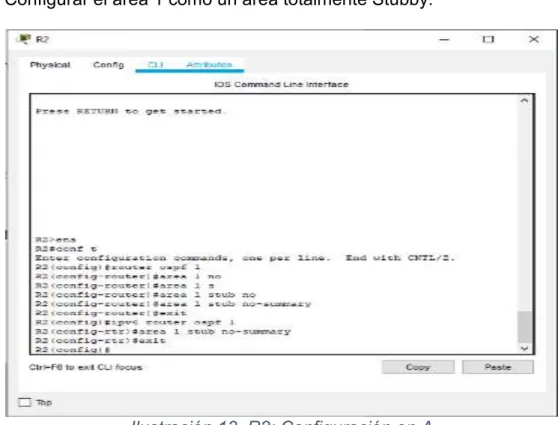
6. Configurar el área 1 como un área totalmente Stubby.
Ilustración 13. R2: Configuración en A
7. Propagar rutas por defecto de IPv4 y IPv6 en R3 al interior del dominio OSPFv3. Nota: Es importante tener en cuenta que una ruta por defecto es diferente a la definición de rutas estáticas.
22
8. Realizar la configuración del protocolo EIGRP para IPv4 como IPv6. Configurar la interfaz F0/0 de R1 y la conexión entre R1 y R2 para EIGRP con el sistema autónomo 101. Asegúrese de que el resumen automático está desactivado.
Ilustración 15. R1: configuración del protocolo EIGRP
9. Configurar las interfaces pasivas para EIGRP según sea apropiado.
23
10. En R2, configurar la redistribución mutua entre OSPF y EIGRP para IPv4 e IPv6. Asignar métricas apropiadas cuando sea necesario.
Ilustración 17. R2: Configuración entre OSPF y EIGRP
11. En R2, de hacer publicidad de la ruta 192.168.3.0/24 a R1 mediante una lista de distribución y ACL.
24
Parte 2: Verificar conectividad de red y control de la trayectoria.
a) Registrar las tablas de enrutamiento en cada uno de los Routers, acorde con los parámetros de configuración establecidos en el escenario propuesto.
Ilustración 19. R1: Enrutamiento
25
Ilustración 21. R2: Enrutamiento
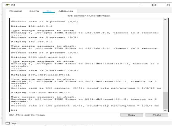
b) Verificar comunicación entre Routers mediante el comando ping y traceroute
Router 1
26
c) Verificar que las rutas filtradas no están presentes en las tablas de enrutamiento de los Routers correctas.
27
1.1.2. ESCENARIO COMANDOS 1
router#ena router#conf t
Enter configuration commands, one per line. End with CNTL/Z. router(config)#host R1
R1(config)#int g0/0
R1(config-if)#ip add 192.168.110.1 255.255.255.0 R1(config-if)#ipv6 add 2001:DB8:ACAD:110::1/64 R1(config-if)#NO SHUT
R1(config-if)#EXIT R1(config)#INT S0/0/0
R1(config-if)#IP ADD 192.168.9.1 255.255.255.252 R1(config-if)#IPV6 ADD 2001:DB8:ACAD:90::1/64 R1(config-if)#NO SHUT
R1(config-if)#EXIT R1(config)#INT S0/0/0
R1(config-if)#CLOC RATE 64000 R1(config-if)#BAND 128
R1(config-if)#EXIT
R1(config)#ROUTER EIGRP 101
R1(config-router)#NETW 192.168.9.0 0.0.0.3 R1(config-router)#NETW 192.168.110.0 0.0.0.255 R1(config-router)#EIGRP ROUTE
% Incomplete command.
28 R1(config)#ipv6 router eigrp 101
R1(config-rtr)#eigrp router-id 1.1.1.1 R1(config-rtr)#exit R1(config)#int g0/0 R1(config-if)#pass R1(config-if)#passive R1(config-if)#passive-interface ^
% Invalid input detected at '^' marker. R1(config-if)#passive-interfaceexit ^
% Invalid input detected at '^' marker. R1(config-if)#exit
R1(config)#router eigrp 101 R1(config-router)#pass
R1(config-router)#passive-interface g0/0 R1(config-router)#exit
R1(config)#
R1#SHOW IP ROU
29 P - periodic downloaded static route
Gateway of last resort is not set
192.168.9.0/24 is variably subnetted, 2 subnets, 2 masks C 192.168.9.0/30 is directly connected, Serial0/0/0
L 192.168.9.1/32 is directly connected, Serial0/0/0
R1#PING 192.168.110.1
Type escape sequence to abort.
Sending 5, 100-byte ICMP Echos to 192.168.110.1, timeout is 2 seconds: ...
Success rate is 0 percent (0/5)
R1#PING 192.168.9.1
Type escape sequence to abort.
Sending 5, 100-byte ICMP Echos to 192.168.9.1, timeout is 2 seconds: !!!!!
Success rate is 100 percent (5/5), round-trip min/avg/max = 2/3/5 ms
ROUTER 2
ROUTER#CONF T
Enter configuration commands, one per line. End with CNTL/Z. ROUTER(config)#HOSTNA R2
30 R2(config-if)#IP ADD 192.168.2.1 255.255.255.0 R2(config-if)#IPV6 ADD 2001:DB8:ACAD:B::1/64 R2(config-if)#NO SHUT
R2(config-if)#EXIT R2(config)#INT S0/0/0
R2(config-if)#IP ADD 192.168.9.2 255.255.255.252 R2(config-if)#IPV6 ADD 2001:DB8:ACAD:90::2/64 R2(config-if)#NO SHUT
R2(config-if)#EXIT R2(config)#INT S0/0/1
R2(config-if)#IP ADD 192.168.9.5 255.255.255.252 R2(config-if)#IPV6 ADD 2001:DB8:ACAD:91::1/64 R2(config-if)#NO SHUT R2(config-if)#EXIT R2(config)#INT S0/0/0 R2(config-if)#BAND 128 R2(config-if)#EXIT R2(config)#INT S0/0/1 R2(config-if)#BAND 128
R2(config-if)#CLOCK RAT 64000 R2(config-if)#EXIT
R2(config)#ROUTER OSPF 3 R2(config-router)#EXIT
R2(config)#ROUTER OSPF 1
R2(config-router)#ROUITER-ID 2.2.2.2 ^
31 R2(config-router)#EXIT
R2(config)#IPV6 ROUTER OSPF 1 R2(config-rtr)#ROUTER-ID 2.2.2.2 R2(config-rtr)#EXIT
R2(config)#ROUTER OSPF 1
R2(config-router)#ROUTER-ID 2.2.2.2
R2(config-router)#NET 192.168.9.0 255.255.255.252 AREA 0 R2(config-router)#NET 192.168.110.0 255.255.255.0 AREA 0 R2(config-router)#EXIT
R2(config)#ROUTER OSPF 1
R2(config-router)#AREA 1 STUB NO-SUMMA R2(config-router)#EXIT
R2(config)#IPV6 ROUTER OSPF 1 R2(config-rtr)#AREA 1 STUB NO-SUMM R2(config-rtr)#EXIT
R2(config)#ROUTER OSPF 1
R2(config-router)#REDISTRIBUTE EIGRP 101 SUBN R2(config-router)#EXIT
R2(config)#ROUTER EIGRP 1
R2(config-router)#REDISTRIBUTE OSPF 1 METRIC 10000 100 255 1 1500 R2(config-router)#EXIT
R2(config)#ROUTER EIGRP 101
R2(config-router)#REDISTRIBUTE OSPF 1 METRIC 10000 100 255 1 1500 R2(config-router)#EXI
R2(config)#IPV6 ROUTER EIGRP 101
R2(config-rtr)#REDISTRIBUTE OSPF 1 METRIC 10000 100 255 1 1500 R2(config-rtr)#EXIT
32 R2(config)#ACCESS-LIST 1 PERMIT ANY R2(config)#EXIT
R2#
%SYS-5-CONFIG_I: Configured from console by console
R2#SHOW IP ROUT
Codes: L - local, C - connected, S - static, R - RIP, M - mobile, B - BGP D - EIGRP, EX - EIGRP external, O - OSPF, IA - OSPF inter area N1 - OSPF NSSA external type 1, N2 - OSPF NSSA external type 2 E1 - OSPF external type 1, E2 - OSPF external type 2, E - EGP i - IS-IS, L1 - IS-IS level-1, L2 - IS-IS level-2, ia - IS-IS inter area * - candidate default, U - per-user static route, o - ODR
P - periodic downloaded static route
Gateway of last resort is not set
192.168.9.0/24 is variably subnetted, 4 subnets, 2 masks C 192.168.9.0/30 is directly connected, Serial0/0/0
L 192.168.9.2/32 is directly connected, Serial0/0/0 C 192.168.9.4/30 is directly connected, Serial0/0/1 L 192.168.9.5/32 is directly connected, Serial0/0/1
R2#SHOW IP PROTOCOL
Routing Protocol is "eigrp 1 "
33
Default networks accepted from incoming updates Redistributing: eigrp 1, ospf 1
EIGRP-IPv4 Protocol for AS(1)
Metric weight K1=1, K2=0, K3=1, K4=0, K5=0 NSF-aware route hold timer is 240
Router-ID: 192.168.2.1 Topology : 0 (base) Active Timer: 3 min
Distance: internal 90 external 170 Maximum path: 4
Maximum hopcount 100 Maximum metric variance 1
Automatic Summarization: disabled Automatic address summarization: Maximum path: 4
Routing for Networks:
Routing Information Sources:
ROUTER 3 router#conf t
Enter configuration commands, one per line. End with CNTL/Z. router(config)#int g0/0
router(config-if)#ip add 192.168.3.1 255.255.255.0 router(config-if)#ipv6 add 2001:DB8:ACAD:C::1/64 router(config-if)#NO SHUT
34
R3(config-if)#IP ADD 192.168.9.6 255.255.255.252 R3(config-if)#IPV6 ADD 2001:DB8:ACAD:91::2/64 R3(config-if)#N SHUT
R3(config-if)#EXIT R3(config)#INT S0/0/1 R3(config-if)#BAND 128 R3(config-if)#EXIT
R3(config)#ROUTER OSPF 1
R3(config-router)#ROUTER-ID 3.3.3.3 R3(config-router)#PASSIVE-IN G0/0 R3(config-router)#EXIT
R3(config)#IPV6 ROUTER OSPF 1 R3(config-rtr)#ROUTER-ID 3.3.3.3 R3(config-rtr)#PASSIVE-IN G0/0 R3(config-rtr)#EXIT
R3(config)#ROUTER OSPF 1
R3(config-router)#ROUTER-ID 3.3.3.3
R3(config-router)#NET 192.168.9.4 255.255.255.252 AREA 0 R3(config-router)#NET 192.168.3.0 255.255.255.0 AREA 0 R3(config-router)#EXIT
R3(config)#ROUTER OSPF 1 R3(config-router)#DEFAUL
R3(config-router)#DEFAULt-information ORIGI R3(config-router)#EXIT
R3(config)#IPV6 ROUTER OSPF 1
R3(config-rtr)#DEFAULt-information ORIGI R3(config-rtr)#EXIT
35 SHOW IP ROUTE
Codes: L - local, C - connected, S - static, R - RIP, M - mobile, B - BGP D - EIGRP, EX - EIGRP external, O - OSPF, IA - OSPF inter area N1 - OSPF NSSA external type 1, N2 - OSPF NSSA external type 2 E1 - OSPF external type 1, E2 - OSPF external type 2, E - EGP i - IS-IS, L1 - IS-IS level-1, L2 - IS-IS level-2, ia - IS-IS inter area * - candidate default, U - per-user static route, o - ODR
P - periodic downloaded static route
Gateway of last resort is not set
192.168.9.0/24 is variably subnetted, 2 subnets, 2 masks C 192.168.9.4/30 is directly connected, Serial0/0/1
L 192.168.9.6/32 is directly connected, Serial0/0/1
R3#SHOW IP PROTOCO
Routing Protocol is "ospf 1"
Outgoing update filter list for all interfaces is not set Incoming update filter list for all interfaces is not set Router ID 3.3.3.3
Number of areas in this router is 1. 1 normal 0 stub 0 nssa Maximum path: 4
Routing for Networks: 192.168.9.4 0.0.0.3 area 0 192.168.3.0 0.0.0.255 area 0 Passive Interface(s):
36 Routing Information Sources:
Gateway Distance Last Update 3.3.3.3 110 00:28:52
37
1.2. Prueba de Habilidades - Escenario 2
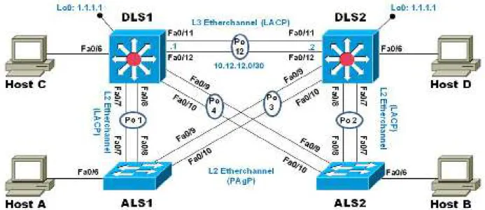
Una empresa de comunicaciones presenta una estructura Core acorde a la topología de red, en donde el estudiante será el administrador de la red, el cual deberá configurar e interconectar entre sí cada uno de los dispositivos que forman parte del escenario, acorde con los lineamientos establecidos para el direccionamiento IP, etherchannels, VLANs y demás aspectos que forman parte del escenario propuesto.
1.2.1. Topología de red 2
Ilustración 24. Topología de Red E2
38
Parte 1: Configurar la red de acuerdo con las especificaciones.
a) Apagar todas las interfaces en cada switch.
Ilustración 26. Switch DLS1: Apagando interfaces
39
Ilustración 28. Switch ALS1: Apagando interfaces
40
b) Asignar un nombre a cada switch acorde al escenario establecido.
Ilustración 30. Switch DLS1: Establecido un nombre
41
Ilustración 32. Switch ALS1: Establecido un nombre
42
c) Configurar los puertos troncales y Port-channels tal como se muestra en el diagrama.
1. La conexión entre DLS1 y DLS2 será un EtherChannel capa-3 utilizando LACP. Para DLS1 se utilizará la dirección IP 10.12.12.1/30 y para DLS2 utilizará 10.12.12.2/30.
2.
Ilustración 34. Switch DLS1: Realizando Conexión
43
3. Los Port-channels en las interfaces Fa0/7 y Fa0/8 utilizarán LACP.
Ilustración 36. Switch DLS1: Configuración de los Port-channels en las interfaces Fa0/7 y Fa0/8 utilizará LACP
44
Ilustración 38. Switch ALS1: Configuración de los Port-channels en las interfaces Fa0/7 y Fa0/8 utilizará LACP
45
4. Los Port-channels en las interfaces F0/9 y fa0/10 utilizará PAgP.
Ilustración 40. Switch DLS1: Configuración de los Port-channels en las interfaces F0/9 y fa0/10 utilizará PAgP
46
Ilustración 42. Switch ALS1: Configuración de los Port-channels en las interfaces F0/9 y fa0/10 utilizará PAgP
47
5. Todos los puertos troncales serán asignados a la VLAN 800 como la VLAN nativa.
Ilustración 44. Switch DLS1: Asignación
48
Ilustración 46. Switch DLS2: Asignación
49
Ilustración 48.Switch DLS2: Asignación
50
Ilustración 50. Switch ALS1: Asignación
51
Ilustración 52. Switch ALS2: Asignación
52
d) Configurar DLS1, ALS1, y ALS2 para utilizar VTP versión 3 1. Utilizar el nombre de dominio UNAD con la contraseña cisco123
Ilustración 54. Switch DLS1: Configuración de Nombre y dominio
2. Configurar DLS1 como servidor principal para las VLAN.
53
3. Configurar ALS1 y ALS2 como clientes VTP.
Ilustración 56. Switch ALS1: Configuración ALS1 como clientes VTP
54
e) Configurar en el servidor principal las siguientes VLAN:
Tabla 1. Configuración en el servidor principal las siguientes VLAN
Número de VLAN
Nombre de VLAN
Número de VLAN
Nombre de VLAN
800 NATIVA 434 ESTACIONAMIENTO
12 EJECUTIVOS 123 MANTENIMIENTO
234 HUESPEDES 1010 VOZ
1111 VIDEONET 3456 ADMINISTRACIÓN
55 f) En DLS1, suspender la VLAN 434.
Ilustración 59. Switch DLS1: Suspender la VLAN 434
56
g) Configurar DLS2 en modo VTP transparente VTP utilizando VTP versión 2, y configurar en DLS2 las mismas VLAN que en DLS1.
Ilustración 61.Switch DLS2: Configuración DLS2 en modo VT
h) Suspender VLAN 434 en DLS2.
57
Ilustración 63. Switch DLS2: Suspendiendo VLAN
i) En DLS2, crear VLAN 567 con el nombre de CONTABILIDAD. La VLAN de CONTABILIDAD no podrá estar disponible en cualquier otro Switch de la red.
58
j) Configurar DLS1 como Spanning tree root para las VLAN 1, 12, 434, 800, 1010, 1111 y 3456 y como raíz secundaria para las VLAN 123 y 234.
Ilustración 65. Switch DLS1: Configuración como Spanning tree root
k) Configurar DLS2 como Spanning tree root para las VLAN 123 y 234 y como una raíz secundaria para las VLAN 12, 434, 800, 1010, 1111 y 3456.
59
l) Configurar todos los puertos como troncales de tal forma que solamente las VLAN que se han creado se les permitirá circular a través de éstos puertos.
Ilustración 67. Switch DLS1: Configuración los puertos
60
Ilustración 69. Switch ALS1: Configuración los puertos
61
m) Configurar las siguientes interfaces como puertos de acceso, asignados a las VLAN de la siguiente manera:
Tabla 2. Configuraciones de las interfaces como puertos de acceso
Interfaz DLS1 DLS2 ALS1 ALS2
Interfaz Fa0/6
3456 12 , 1010 123, 1010 234 Interfaz
Fa0/15
1111 1111 1111 1111
Interfaces F0 /16-18
567
62
Ilustración 72. Switch DLS2: Configuración de interfaces
63
Ilustración 74.Switch ALS1: Configuración de interfaces
Parte 2: conectividad de red de prueba y las opciones configuradas.
a) Verificar la existencia de las VLAN correctas en todos los switches y la asignación de puertos troncales y de acceso
64
Ilustración 76. Switch DLS2: Verificación la existencia de las VLAN
65
Ilustración 78. Switch ALS2: Verificación la existencia de las VLAN
b) Verificar que el EtherChannel entre DLS1 y ALS1 está configurado correctamente
66
Ilustración 80. Switch DLS1: Verificación
c) Verificar la configuración de Spanning tree entre DLS1 o DLS2 para cada VLAN.
67
Ilustración 82. Switch DLS1: Configuración de Spanning tree
68
Ilustración 84. Switch DLS2: Configuración de Spanning tree
69
Ilustración 86.Switch ALS1: Configuración de Spanning tree
70
71
1.2.2. ESCENARIO COMANDOS 2
DLS1 swtich>ena swtich#conf t
Enter configuration commands, one per line. End with CNTL/Z. swtich(config)#int rang f0/1-24, g0/1-2
swtich(config-if-range)#shutdown swtich(config-if-range)#
%LINK-5-CHANGED: Interface FastEthernet0/6, changed state to administratively down
%LINEPROTO-5-UPDOWN: Line protocol on Interface FastEthernet0/6, changed state to down
%LINK-5-CHANGED: Interface FastEthernet0/7, changed state to administratively down
%LINEPROTO-5-UPDOWN: Line protocol on Interface FastEthernet0/7, changed state to down
%LINK-5-CHANGED: Interface FastEthernet0/8, changed state to administratively down
%LINEPROTO-5-UPDOWN: Line protocol on Interface FastEthernet0/8, changed state to down
%LINK-3-UPDOWN: Interface Port-channel1, changed state to down
%LINEPROTO-5-UPDOWN: Line protocol on Interface Port-channel1, changed state to down
%LINK-5-CHANGED: Interface FastEthernet0/9, changed state to administratively down
%LINEPROTO-5-UPDOWN: Line protocol on Interface FastEthernet0/9, changed state to down
%LINK-5-CHANGED: Interface FastEthernet0/10, changed state to administratively down
%LINEPROTO-5-UPDOWN: Line protocol on Interface FastEthernet0/10, changed state to down
%LINK-5-CHANGED: Interface FastEthernet0/11, changed state to administratively down
%LINEPROTO-5-UPDOWN: Line protocol on Interface FastEthernet0/11, changed state to down
%LINK-5-CHANGED: Interface FastEthernet0/12, changed state to administratively down
%LINEPROTO-5-UPDOWN: Line protocol on Interface FastEthernet0/12, changed state to down
72 DSL1(config)#
DSL1(config)#INT RANG F0/7-8
DSL1(config-if-range)#CHANNEL-PROTOCOL LACP DSL1(config-if-range)#CHANNEL-GR
DSL1(config-if-range)#CHANNEL-GRoup 2 MODE ACTIV DSL1(config-if-range)#NO SHUT
DSL1(config-if-range)#
%LINK-5-CHANGED: Interface FastEthernet0/7, changed state to up
%LINEPROTO-5-UPDOWN: Line protocol on Interface FastEthernet0/7, changed state to up
%LINK-5-CHANGED: Interface FastEthernet0/8, changed state to up
%LINEPROTO-5-UPDOWN: Line protocol on Interface FastEthernet0/8, changed state to up
%LINK-5-CHANGED: Interface Port-channel2, changed state to up
%LINEPROTO-5-UPDOWN: Line protocol on Interface Port-channel2, changed state to up
DSL1(config-if-range)#EXIT
DSL1(config)#INT RANGE F0/9-10
DSL1(config-if-range)#CHANNEL-PROTOCOL PAGP DSL1(config-if-range)#CHANNEL-GRoup 2 MODE DESIRA DSL1(config-if-range)#NO SHUT
DSL1(config-if-range)#
%LINK-5-CHANGED: Interface FastEthernet0/9, changed state to up
%LINEPROTO-5-UPDOWN: Line protocol on Interface FastEthernet0/9, changed state to up
%LINK-5-CHANGED: Interface FastEthernet0/10, changed state to up
%LINEPROTO-5-UPDOWN: Line protocol on Interface FastEthernet0/10, changed state to up
DSL1(config-if-range)#EXIT DSL1(config)#INT RANG F0/7-12 DSL1(config-if-range)#SW
DSL1(config-if-range)#SWitchport TRUNK ENCAP D DSL1(config-if-range)#SWitchport TRUNK ENCAP Dot1q % Interface range command failed for FastEthernet0/11 % Command failed on interface FastEthernet0/11. Aborting DSL1(config)#
%LINEPROTO-5-UPDOWN: Line protocol on Interface FastEthernet0/7, changed state to down
%LINEPROTO-5-UPDOWN: Line protocol on Interface FastEthernet0/7, changed state to up
%LINEPROTO-5-UPDOWN: Line protocol on Interface FastEthernet0/9, changed state to down
73
%LINEPROTO-5-UPDOWN: Line protocol on Interface FastEthernet0/10, changed state to down
%LINEPROTO-5-UPDOWN: Line protocol on Interface FastEthernet0/10, changed state to up%LINK-3-UPDOWN: Interface Port-channel2, changed state to down %LINEPROTO-5-UPDOWN: Line protocol on Interface Port-channel2, changed state to down
%LINEPROTO-5-UPDOWN: Line protocol on Interface FastEthernet0/8, changed state to down
%LINEPROTO-5-UPDOWN: Line protocol on Interface FastEthernet0/8, changed state to up
DSL1(config)#
%LINK-5-CHANGED: Interface Port-channel2, changed state to up
%LINEPROTO-5-UPDOWN: Line protocol on Interface Port-channel2, changed state to up
DSL1(config-if-range)#SWitchport TRUNK NATIVE VLAN 800 DSL1(config-if-range)#SWitchport MODE TRUNK
DSL1#ENA DSL1#CONF T
Enter configuration commands, one per line. End with CNTL/Z. DSL1(config)#VTP DOMAIN UNAD
Domain name already set to UNAD. DSL1(config)#VTP PASS cisco123 Password already set to cisco123 DSL1(config)#VTP MODE SERVER Device mode already VTP SERVER. DSL1(config)#
DSL1#ENA DSL1#CONF T
Enter configuration commands, one per line. End with CNTL/Z. DSL1(config)#VTP DOMAIN UNAD
Domain name already set to UNAD. DSL1(config)#VTP PASS cisco123 Password already set to cisco123 DSL1(config)#VTP MODE SERVER Device mode already VTP SERVER. DSL1(config)#
DSL1(config)#
DSL1(config)#VLAN 111
DSL1(config-vlan)#NAME VIDEONET
VLAN #11 and #111 have an identical name: VIDEONET DSL1(config-vlan)#VLAN 123
DSL1(config-vlan)#NAME MANTENIMIENTO DSL1(config-vlan)#VLAN 101
DSL1(config-vlan)#NAME VOZ
74 DSL1(config-vlan)#VLAN 345
DSL1(config-vlan)#NAME ADMINISTRACION
VLAN #34 and #345 have an identical name: ADMINISTRACION DSL1(config-vlan)#VLAN 800 DSL1(config-vlan)#NAME NATIVA DSL1(config-vlan)#VLAN 12 DSL1(config-vlan)#NAME EJECUTIVOS DSL1(config-vlan)#VLAN 234 DSL1(config-vlan)#NAME HUESPEDES DSL1(config-vlan)#VLAN 434 DSL1(config-vlan)#NAME ESTACIONAMIENTO DSL1(config-vlan)#STATE SUSPEND DSL1(config)#SPAN
DSL1(config)#SPANning-tree VLAN 1 ROOT PRIMARY DSL1(config)#SPANning-tree VLAN 12 ROOT PRIMARY DSL1(config)#SPANning-tree VLAN 434 ROOT PRIMARY DSL1(config)#SPANning-tree VLAN 800 ROOT PRIMARY DSL1(config)#SPANning-tree VLAN 101 ROOT PRIMARY DSL1(config)#SPANning-tree VLAN 123 ROOT PRIMARY DSL1(config)#SPANning-tree VLAN 234 ROOT PRIMARY DSL1(config)#SPANning-tree VLAN 123 ROOT SECONDARY DSL1(config)#SPANning-tree VLAN 234 ROOT SECONDARY DSL1(config)#
DSL1(config)#INT F0/6
DSL1(config-if)#SWITCHPORT ACCES VLAN 345 DSL1(config-if)#NO SHUT
DSL1(config-if)#
%LINK-5-CHANGED: Interface FastEthernet0/6, changed state to up
%LINEPROTO-5-UPDOWN: Line protocol on Interface FastEthernet0/6, changed state to up
DSL1(config-if)#INT F0/15
DSL1(config-if)#SWITCHPORT ACCES VLAN 111 DSL1(config-if)#NO SHUT
%LINK-5-CHANGED: Interface FastEthernet0/15, changed state to down DSL1(config-if)#SHOW VLAN
DSL1#SHOW ETHErchannel SUMMAry DSL1#SHO SPanning-tree
DLS2 switch>ena switch#conf t
75 switch(config-if-range)#shut
%LINK-5-CHANGED: Interface FastEthernet0/11, changed state to administratively down
%LINK-5-CHANGED: Interface FastEthernet0/12, changed state to administratively down
switch(config-if-range)#
%LINK-5-CHANGED: Interface FastEthernet0/6, changed state to administratively down
%LINEPROTO-5-UPDOWN: Line protocol on Interface FastEthernet0/6, changed state to down
%LINK-5-CHANGED: Interface FastEthernet0/7, changed state to administratively down
%LINEPROTO-5-UPDOWN: Line protocol on Interface FastEthernet0/7, changed state to down
%LINK-5-CHANGED: Interface FastEthernet0/8, changed state to administratively down
%LINEPROTO-5-UPDOWN: Line protocol on Interface FastEthernet0/8, changed state to down
%LINK-3-UPDOWN: Interface Port-channel2, changed state to down
%LINEPROTO-5-UPDOWN: Line protocol on Interface Port-channel2, changed state to down
%LINK-5-CHANGED: Interface FastEthernet0/9, changed state to administratively down
%LINEPROTO-5-UPDOWN: Line protocol on Interface FastEthernet0/9, changed state to down
%LINK-5-CHANGED: Interface FastEthernet0/10, changed state to administratively down
%LINEPROTO-5-UPDOWN: Line protocol on Interface FastEthernet0/10, changed state to down
switch(config-if-range)#EXIT switch(config)#INT G0/2 switch(config-if)#SHUT switch(config-if)#EXIT switch(config)#HOST DLS2 DLS2(config)#
%LINK-3-UPDOWN: Interface Port-channel3, changed state to down
%LINEPROTO-5-UPDOWN: Line protocol on Interface Port-channel3, changed state to down
DLS2(config)#INT RANG F0/7-8
DLS2(config-if-range)#CHANNEL-PROTOCOL LACP
DLS2(config-if-range)#CHANNEL-GROUP 2 MODE ACTIVE DLS2(config-if-range)#NO SHUT
DLS2(config-if-range)#
76
%LINEPROTO-5-UPDOWN: Line protocol on Interface FastEthernet0/7, changed state to up
%LINK-5-CHANGED: Interface FastEthernet0/8, changed state to up
%LINEPROTO-5-UPDOWN: Line protocol on Interface FastEthernet0/8, changed state to up
%LINK-5-CHANGED: Interface Port-channel2, changed state to up
%LINEPROTO-5-UPDOWN: Line protocol on Interface Port-channel2, changed state to up
DLS2(config-if-range)#
DLS2(config-if-range)#INT RANG F0/9-10
DLS2(config-if-range)#CHANNEL-PROTOCOL PAGP
DLS2(config-if-range)#CHANNEL-GROUP 2 MODE ACTIVE
Command rejected (the interface Fa0/9 is ): is already part of a channel with a different type of protocol enabled
Command rejected (the interface Fa0/10 is ): is already part of a channel with a different type of protocol enabled
DLS2(config-if-range)#NO SHUT
DLS2(config-if-range)#
%LINK-5-CHANGED: Interface FastEthernet0/9, changed state to up
%LINEPROTO-5-UPDOWN: Line protocol on Interface FastEthernet0/9, changed state to up
%LINK-5-CHANGED: Interface FastEthernet0/10, changed state to up
%LINEPROTO-5-UPDOWN: Line protocol on Interface FastEthernet0/10, changed state to up
%LINK-5-CHANGED: Interface Port-channel3, changed state to up
%LINEPROTO-5-UPDOWN: Line protocol on Interface Port-channel3, changed state to up
DLS2(config-if-range)#INT RANG F0/9-10
DLS2(config-if-range)#CHANNEL-PROTOCOL PAGP
DLS2(config-if-range)#CHANNEL-GROUP 2 MODE ACTIVE
Command rejected (the interface Fa0/9 is ): is already part of a channel with a different type of protocol enabled
Command rejected (the interface Fa0/10 is ): is already part of a channel with a different type of protocol enabled
DLS2(config-if-range)#NO SHUT DLS2(config-if-range)#
%LINK-5-CHANGED: Interface FastEthernet0/9, changed state to up
%LINEPROTO-5-UPDOWN: Line protocol on Interface FastEthernet0/9, changed state to up
%LINK-5-CHANGED: Interface FastEthernet0/10, changed state to up
%LINEPROTO-5-UPDOWN: Line protocol on Interface FastEthernet0/10, changed state to up
77
%LINEPROTO-5-UPDOWN: Line protocol on Interface Port-channel3, changed state to up
DLS2(config-if-range)#EXIT DLS2(config)#INT RAN F0/7-12
DLS2(config-if-range)#SWITCHPORT TRUNK ENCAP D DLS2(config-if-range)#SWITCHPORT TRUNK ENCAP Dot1q % Interface range command failed for FastEthernet0/11
% Command failed on interface FastEthernet0/11. Aborting DLS2(config)#
%LINEPROTO-5-UPDOWN: Line protocol on Interface FastEthernet0/7, changed state to down
%LINEPROTO-5-UPDOWN: Line protocol on Interface FastEthernet0/7, changed state to up
%LINK-3-UPDOWN: Interface Port-channel2, changed state to down
%LINEPROTO-5-UPDOWN: Line protocol on Interface Port-channel2, changed state to down
%LINEPROTO-5-UPDOWN: Line protocol on Interface FastEthernet0/8, changed state to down
%LINEPROTO-5-UPDOWN: Line protocol on Interface FastEthernet0/8, changed state to up
%LINK-3-UPDOWN: Interface Port-channel3, changed state to down
%LINEPROTO-5-UPDOWN: Line protocol on Interface Port-channel3, changed state to down
DLS2(config)# DLS2#
%SYS-5-CONFIG_I: Configured from console by console
%LINK-5-CHANGED: Interface Port-channel3, changed state to up
%LINEPROTO-5-UPDOWN: Line protocol on Interface Port-channel3, changed state to up
%LINK-5-CHANGED: Interface Port-channel2, changed state to up
%LINEPROTO-5-UPDOWN: Line protocol on Interface Port-channel2, changed state to up
DLS2#ENA DLS2#CONF T
Enter configuration commands, one per line. End with CNTL/Z. DLS2(config)#INT RAN F0/7-12
DLS2(config-if-range)#SWITCHPORT TRUNK NATIVE VLAN 800 % Interface range command failed for FastEthernet0/11
% Command failed on interface FastEthernet0/11. Aborting DLS2(config)#INT RAN F0/7-12
78
%LINEPROTO-5-UPDOWN: Line protocol on Interface FastEthernet0/7, changed state to down
%LINEPROTO-5-UPDOWN: Line protocol on Interface FastEthernet0/7, changed state to up
%LINK-3-UPDOWN: Interface Port-channel2, changed state to down
%LINEPROTO-5-UPDOWN: Line protocol on Interface Port-channel2, changed state to down
%LINEPROTO-5-UPDOWN: Line protocol on Interface FastEthernet0/8, changed state to down
%LINEPROTO-5-UPDOWN: Line protocol on Interface FastEthernet0/8, changed state to up
%LINK-3-UPDOWN: Interface Port-channel3, changed state to down
%LINEPROTO-5-UPDOWN: Line protocol on Interface Port-channel3, changed state to down
DLS2(config)#
%LINK-5-CHANGED: Interface Port-channel3, changed state to up
%LINEPROTO-5-UPDOWN: Line protocol on Interface Port-channel3, changed state to up
DLS2(config)#INT RAN F0/7-12
DLS2(config-if-range)#SWITCHPORT NO
DLS2(config-if-range)#SWITCHPORT NOnegotiate % Interface range command failed for FastEthernet0/11 % Command failed on interface FastEthernet0/11. Aborting DLS2(config)#NO SHUT
% Invalid input detected at '^' marker. DLS2(config)#INT RAN F0/7-12 DLS2(config-if-range)#
%LINK-5-CHANGED: Interface Port-channel2, changed state to up
%LINEPROTO-5-UPDOWN: Line protocol on Interface Port-channel2, changed state to up
NO SHUT
%LINK-5-CHANGED: Interface FastEthernet0/11, changed state to down %LINK-5-CHANGED: Interface FastEthernet0/12, changed state to down DLS2(config-if-range)#
DLS2(config)#VTP VERSION 2 DLS2(config)#VTP MODE TRANSPA
79
VLAN #11 and #111 have an identical name: VIDEONET DLS2(config-vlan)#VLAN 123
DLS2(config-vlan)#NAME MANTENIMIENTO DLS2(config-vlan)#VLAN 101
DLS2(config-vlan)#NAME VOZ
VLAN #10 and #101 have an identical name: VOZ DLS2(config-vlan)#VLAN 345
DLS2(config-vlan)#NAME ADMINISTRACION
VLAN #34 and #345 have an identical name: ADMINISTRACION DLS2(config-vlan)#VLAN 434 DLS2(config-vlan)#NAME ESTACIONAMIENTO DLS2(config-vlan)#STATE SUSPEND DLS2(config-vlan)#VLAN 567 DLS2(config-vlan)#NAME CONTABILIDAD DLS2(config-vlan)# DLS2#CONF TER
Enter configuration commands, one per line. End with CNTL/Z. DLS2(config)#SPAN
DLS2(config)#SPANning-tree VLAN 123 ROOT PRIMARY DLS2(config)#SPANning-tree VLAN 234 ROOT PRIMARY DLS2(config)#SPANning-tree VLAN 12 ROOT PRIMARY DLS2(config)#SPANning-tree VLAN 12 ROOT SECONDARY DLS2(config)#SPANning-tree VLAN 434 ROOT SECONDARY DLS2(config)#SPANning-tree VLAN 800 ROOT SECONDARY DLS2(config)#SPANning-tree VLAN 101 ROOT SECONDARY DLS2(config)#SPANning-tree VLAN 111 ROOT SECONDARY DLS2(config)#SPANning-tree VLAN 345 ROOT SECONDARY DLS2(config)#INT F0/6
DLS2(config-if)#SWITCHPORT ACCESS VLAN 12 DLS2(config-if)#SWITCHPORT ACCESS VLAN 101 DLS2(config-if)#NO SHUT
DLS2(config-if)#
%LINK-5-CHANGED: Interface FastEthernet0/6, changed state to up
%LINEPROTO-5-UPDOWN: Line protocol on Interface FastEthernet0/6, changed state to up
DLS2(config-if)#INT F0/15
DLS2(config-if)#SWITCHPORT ACCESS VLAN 111 DLS2(config-if)#NO SHUT
%LINK-5-CHANGED: Interface FastEthernet0/15, changed state to down DLS2(config-if)#EXIT
DLS2(config)#INT RANG F0/16-18
DLS2(config-if-range)#SWITCHPORT ACCESS VLAN 567 DLS2(config-if-range)#NO SHUT
80
%LINK-5-CHANGED: Interface FastEthernet0/18, changed state to down DLS2#SHOW VLAN
DLS2#SHOW SPAnning-tree ALS1
SWITCH>EN SWITCH#CONF T
Enter configuration commands, one per line. End with CNTL/Z. SWITCH(config)#INT RAN F0/1-24, G0/1-2
SWITCH(config-if-range)#SHUT SWITCH(config-if-range)#
%LINK-5-CHANGED: Interface FastEthernet0/6, changed state to administratively down
%LINEPROTO-5-UPDOWN: Line protocol on Interface FastEthernet0/6, changed state to down
%LINK-5-CHANGED: Interface FastEthernet0/7, changed state to administratively down
%LINEPROTO-5-UPDOWN: Line protocol on Interface FastEthernet0/7, changed state to down
%LINK-5-CHANGED: Interface FastEthernet0/8, changed state to administratively down
%LINEPROTO-5-UPDOWN: Line protocol on Interface FastEthernet0/8, changed state to down
%LINK-3-UPDOWN: Interface Port-channel1, changed state to down
%LINEPROTO-5-UPDOWN: Line protocol on Interface Port-channel1, changed state to down
%LINK-5-CHANGED: Interface FastEthernet0/9, changed state to administratively down
%LINEPROTO-5-UPDOWN: Line protocol on Interface FastEthernet0/9, changed state to down
%LINK-5-CHANGED: Interface FastEthernet0/10, changed state to administratively down
%LINEPROTO-5-UPDOWN: Line protocol on Interface FastEthernet0/10, changed state to down
SWITCH(config)#HOST ALS1 ALS1(config)#INT RAN F0/9-10
ALS1(config-if-range)#CHANNEL-PROTOCOL PAGP
ALS1(config-if-range)#CHANNEL-GROUP 2 MODE DESIRABL ALS1(config-if-range)#NO SHUT
ALS1(config-if-range)#
%LINK-5-CHANGED: Interface FastEthernet0/9, changed state to up
%LINEPROTO-5-UPDOWN: Line protocol on Interface FastEthernet0/9, changed state to up
81
%LINEPROTO-5-UPDOWN: Line protocol on Interface FastEthernet0/10, changed state to up
%LINK-5-CHANGED: Interface Port-channel2, changed state to up
%LINEPROTO-5-UPDOWN: Line protocol on Interface Port-channel2, changed state to up
ALS1(config)#INT RAN F0/7-10
ALS1(config-if-range)#SWITCHPORT TRUNK native vlan 800 ALS1(config-if-range)#SWITCHPORT MODE TRUNK
ALS1(config-if-range)#
%LINK-3-UPDOWN: Interface Port-channel2, changed state to down
%LINEPROTO-5-UPDOWN: Line protocol on Interface Port-channel2, changed state to down
ALS1(config-if-range)#EXIT ALS1(config)#VTP VER 2
Cannot modify version in VTP client mode ALS1(config)#VTP MODE CLIE
Device mode already VTP CLIENT. ALS1(config)#INT RAN F0/7-10
ALS1(config-if-range)#SWITCHPORT TRUNK native vlan 800 ALS1(config-if-range)#SWITCHPORT MODE TRUNK
ALS1(config-if-range)#
%LINK-3-UPDOWN: Interface Port-channel2, changed state to down
%LINEPROTO-5-UPDOWN: Line protocol on Interface Port-channel2, changed state to down
ALS1(config-if-range)#
%LINK-5-CHANGED: Interface Port-channel2, changed state to up
%LINEPROTO-5-UPDOWN: Line protocol on Interface Port-channel2, changed state to up
ALS1(config-if-range)#EXIT ALS1(config)#INT F0/6 ALS1(config-if)#SWI
ALS1(config-if)#SWItchport ACCES VLAN 123 ALS1(config-if)#SWItchport ACCES VLAN 101 ALS1(config-if)#NO SHUT
ALS1(config-if)#
%LINK-5-CHANGED: Interface FastEthernet0/6, changed state to up
%LINEPROTO-5-UPDOWN: Line protocol on Interface FastEthernet0/6, changed state to up
ALS1(config-if)#EXIT ALS1(config)#INT F0/15
ALS1(config-if)#SWItchport ACCES VLAN 111 ALS1(config-if)#NO SHUT
82
ALS1(config-if)#SHOW ETHERCHANNEL SUMMARY ALS2
swtich>ENA
swtich#CONF TERM
Enter configuration commands, one per line. End with CNTL/Z. swtich(config)#INT
swtich(config)#INTerface RANG
swtich(config)#INTerface RANGe F0/1-24, G0/1-2 swtich(config-if-range)#SHUT
swtich(config-if-range)#
%LINK-5-CHANGED: Interface FastEthernet0/6, changed state to administratively down
%LINEPROTO-5-UPDOWN: Line protocol on Interface FastEthernet0/6, changed state to down
%LINK-5-CHANGED: Interface FastEthernet0/7, changed state to administratively down
%LINEPROTO-5-UPDOWN: Line protocol on Interface FastEthernet0/7, changed state to down
%LINK-5-CHANGED: Interface FastEthernet0/8, changed state to administratively down
%LINEPROTO-5-UPDOWN: Line protocol on Interface FastEthernet0/8, changed state to down
%LINK-3-UPDOWN: Interface Port-channel2, changed state to down
%LINEPROTO-5-UPDOWN: Line protocol on Interface Port-channel2, changed state to down
%LINK-5-CHANGED: Interface FastEthernet0/9, changed state to administratively down
%LINEPROTO-5-UPDOWN: Line protocol on Interface FastEthernet0/9, changed state to down
%LINK-5-CHANGED: Interface FastEthernet0/10, changed state to administratively down
%LINEPROTO-5-UPDOWN: Line protocol on Interface FastEthernet0/10, changed state to down
swtich(config-if-range)#EXIT swtich(config)#HOST ALS2 ALS2(config)#
ALS2#ENA ALS2#CONF T
Enter configuration commands, one per line. End with CNTL/Z. ALS2(config)#INT RANG F0/7-8
ALS2(config-if-range)#CHANNEL-PROTOCOL LACP ALS2(config-if-range)#CHANNEL-GROUP 2 MODE ACTIV ALS2(config-if-range)#NO SHUT
83
%LINK-5-CHANGED: Interface FastEthernet0/7, changed state to up
%LINEPROTO-5-UPDOWN: Line protocol on Interface FastEthernet0/7, changed state to up
%LINK-5-CHANGED: Interface FastEthernet0/8, changed state to up
%LINEPROTO-5-UPDOWN: Line protocol on Interface FastEthernet0/8, changed state to up
%LINK-5-CHANGED: Interface Port-channel2, changed state to up
%LINEPROTO-5-UPDOWN: Line protocol on Interface Port-channel2, changed state to up
ALS2(config-if-range)#EXIT ALS2(config)#INT RANG F0/9-10
ALS2(config-if-range)#CHANNEL-PROTOCOL PAGP
ALS2(config-if-range)#CHANNEL-GROUP 2 MODE DESIRABLE ALS2(config-if-range)#NO SHUT
ALS2(config-if-range)#
%LINK-5-CHANGED: Interface FastEthernet0/9, changed state to up
%LINEPROTO-5-UPDOWN: Line protocol on Interface FastEthernet0/9, changed state to up
%LINK-5-CHANGED: Interface FastEthernet0/10, changed state to up
%LINEPROTO-5-UPDOWN: Line protocol on Interface FastEthernet0/10, changed state to up
ALS2(config)#INT RANG F0/7-10
ALS2(config-if-range)#SWITCH TRUNK NATIVE VLAN 800 ALS2(config-if-range)#SWITCH MODE TRUNK
ALS2(config-if-range)#
%LINEPROTO-5-UPDOWN: Line protocol on Interface FastEthernet0/7, changed state to down
%LINEPROTO-5-UPDOWN: Line protocol on Interface FastEthernet0/7, changed state to up
%LINEPROTO-5-UPDOWN: Line protocol on Interface FastEthernet0/9, changed state to down
%LINEPROTO-5-UPDOWN: Line protocol on Interface FastEthernet0/9, changed state to up
%LINEPROTO-5-UPDOWN: Line protocol on Interface FastEthernet0/10, changed state to down
%LINEPROTO-5-UPDOWN: Line protocol on Interface FastEthernet0/10, changed state to up
%LINK-3-UPDOWN: Interface Port-channel2, changed state to down
%LINEPROTO-5-UPDOWN: Line protocol on Interface Port-channel2, changed state to down
%LINEPROTO-5-UPDOWN: Line protocol on Interface FastEthernet0/8, changed state to down
%LINEPROTO-5-UPDOWN: Line protocol on Interface FastEthernet0/8, changed state to up
84 ALS2(config-if-range)#NO SHUT
ALS2#ENA ALS2#CONF T
Enter configuration commands, one per line. End with CNTL/Z. ALS2(config)#VTP VERSION 2
Cannot modify version in VTP client mode ALS2(config)#VTP MODE CLIENT
Device mode already VTP CLIENT ALS2>ena
ALS2#conf te
Enter configuration commands, one per line. End with CNTL/Z. ALS2(config)#int f0/15
ALS2(config-if)#switc
ALS2(config-if)#switchport access vlan 234 ALS2(config-if)#no shut
%LINK-5-CHANGED: Interface FastEthernet0/15, changed state to down ALS2(config-if)#exit
ALS2(config)#int f0/15
ALS2(config-if)#switchport access vlan 111 ALS2(config-if)#no shut
85
CONCLUSIONES
Durante el desarrollo de este diplomado CCNP se logró adquirir conocimientos prácticos y teóricos no solo para el desarrollo de esta prueba de habilidades en los dos escenarios propuestos, sino para cualquier otro escenario en el que se puedan administrar equipos tales como routers y enrutadores en diferentes topologías.
Se logró interconectar varias sedes como lo haríamos en un entorno real configurando equipos marca CISCO aprovechando la simulación con el software packet tracer el cual es una muy buena herramienta para entender mejor el funcionamiento de las redes y sus protocolos de enrutamiento como lo son EIGRP Y OSPF, DCHP, comprendiendo mejor los límites y necesidades planteadas en cualquier esquema de configuración o topología. También mediante el Switching y el Routing se logró aumentar la velocidad de acceso a la información administrándola de forma más eficiente.
86
BIBLIOGRAFÍA
Donohue, D. (2017). CISCO Press (Ed). CCNP Quick Reference. Recuperado de https://1drv.ms/b/s!AgIGg5JUgUBthFt77ehzL5qp0OKD
Froom, R., Frahim, E. (2015). CISCO Press (Ed). Campus Network Security. Implementing Cisco IP Switched Networks (SWITCH) Foundation Learning
Guide CCNP SWITCH 300-115. Recuperado de
https://1drv.ms/b/s!AmIJYei-NT1IlnWR0hoMxgBNv1CJ
Froom, R., Frahim, E. (2015). CISCO Press (Ed). First Hop Redundancy Protocols. Implementing Cisco IP Switched Networks (SWITCH) Foundation Learning
Guide CCNP SWITCH 300-115. Recuperado de
https://1drv.ms/b/s!AmIJYei-NT1IlnWR0hoMxgBNv1CJ
Froom, R., Frahim, E. (2015). CISCO Press (Ed). High Availability. Implementing Cisco IP Switched Networks (SWITCH) Foundation Learning Guide CCNP SWITCH 300-115. Recuperado de https://1drv.ms/b/s!AmIJYei-NT1IlnWR0hoMxgBNv1CJ
Froom, R., Frahim, E. (2015). CISCO Press (Ed). Network Management. Implementing Cisco IP Switched Networks (SWITCH) Foundation Learning
Guide CCNP SWITCH 300-115. Recuperado de
https://1drv.ms/b/s!AmIJYei-NT1IlnWR0hoMxgBNv1CJ
Froom, R., Frahim, E. (2015). CISCO Press (Ed). v. Implementing Cisco IP Switched Networks (SWITCH) Foundation Learning Guide CCNP SWITCH 300-115. Recuperado de https://1drv.ms/b/s!AmIJYei-NT1IlnWR0hoMxgBNv1CJ
Hucaby, D. (2015). CISCO Press (Ed). CCNP Routing and Switching SWITCH
300-115 Official Cert Guide. Recuperado de
https://1drv.ms/b/s!AgIGg5JUgUBthF16RWCSsCZnfDo2
Macfarlane, J. (2014). Network Routing Basics : Understanding IP Routing in Cisco
Systems. Recuperado de
http://bibliotecavirtual.unad.edu.co:2048/login?url=http://search.ebscohost.c om/login.aspx?direct=true&db=e000xww&AN=158227&lang=es&site=ehost-live
UNAD (2015). Switch CISCO Security Management [OVA]. Recuperado de